High-effect gas boiler with gas leakage alarm device

An alarm device and gas leakage technology, which is applied to alarms, instruments, fluid heaters, etc., can solve problems such as gas leakage, poor heat preservation effect, and small heating area, so as to increase the temperature raising speed, improve heat preservation effect, and increase supply The effect of thermal area

Inactive Publication Date: 2018-10-26
张凯帆
View PDF0 Cites 1 Cited by
  • Summary
  • Abstract
  • Description
  • Claims
  • Application Information

AI Technical Summary

Problems solved by technology

[0003] However, existing gas-fired boilers still have deficiencies during use. First, the existing gas-fired boilers lack detection devices for gas leakage, which may easily cause boiler operation failures; secondly, the existing boilers use bottom heating, and the heating area Small, low heating efficiency; Finally, the existing boiler is in direct contact with the furnace body, and the heat preservation effect is poor, which indirectly affects the heating effect of the chamber

Method used


Image

  • High-effect gas boiler with gas leakage alarm device
  • High-effect gas boiler with gas leakage alarm device
  • High-effect gas boiler with gas leakage alarm device

Examples


Embodiment 1

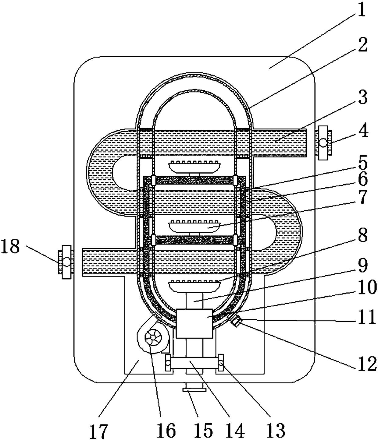
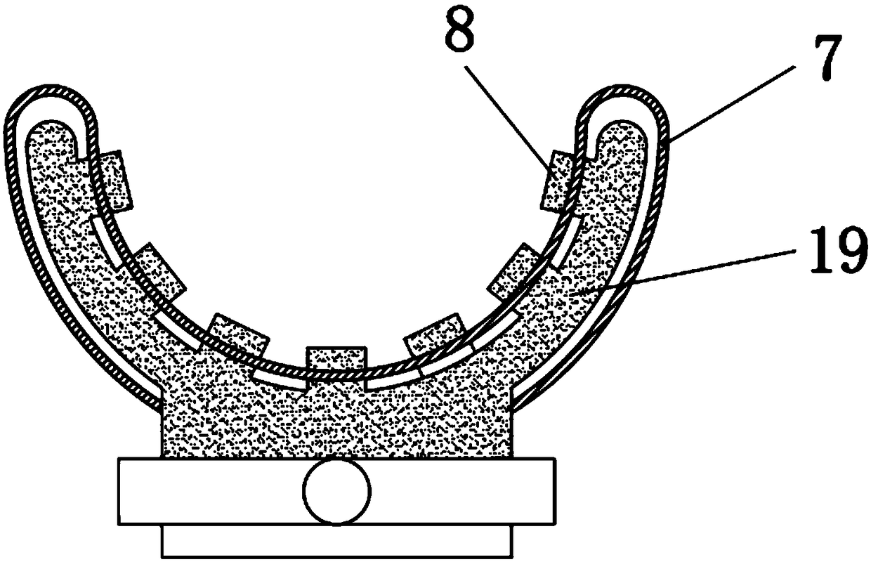
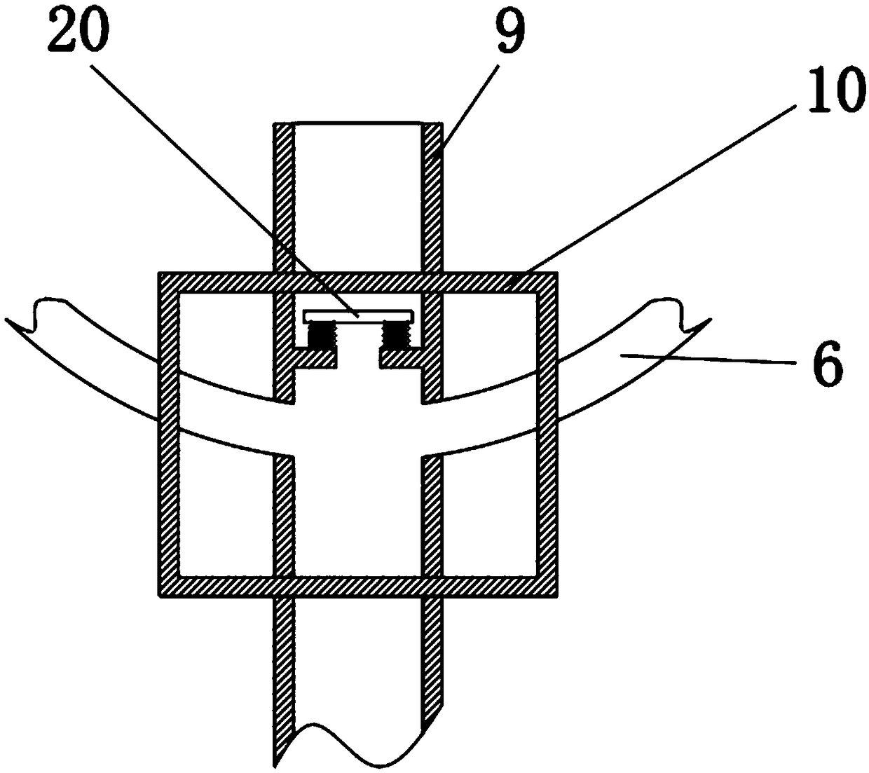
[0029] Embodiment one, with reference to Figure 1-4 , a high-efficiency gas boiler with a gas leakage alarm device, including a furnace body 1, a combustion base 7 and a gas alarm 11, and a gas flow chamber 17 is provided on both sides of the inner bottom of the furnace body 1, and two gas flow chambers There is a ventilation pipe 14 connected between the warehouses 17, and the two ends of the ventilation pipe 14 are provided with a one-way communication valve 13. A chamber 2 is welded inside the furnace body 1, and a gas distribution box 10 is welded at the bottom of the chamber 2 to allow the gas flow A second gas communication pipe 9 is sleeved in the box 10, and both sides of the second gas communication pipe 9 are elastically connected with baffles 20 through springs. One end is connected with a heating water pipe 3 that runs through the furnace body 1 and the chamber 2, and the other end of the heating water pipe 3 is connected with a drain pipe 18. The cross section of...

Embodiment 2

[0030] Embodiment two, refer to figure 1 One end of the bottom of the chamber 2 is connected with an air pump 16, and the other end of the bottom of the chamber 2 is connected with an exhaust pipe 12, and the exhaust pipe 12 is provided with a gas alarm 11. The wall and the outer wall of the heating water pipe 3 all have a gap of 1 cm, and the part of the outer wall of the heating water pipe 3 located in the interior of the chamber 2 is sleeved with thermal insulation cotton 5. When the air pump 16 works, the gas flows in the chamber 2, and It is discharged through the exhaust pipe 12 and is detected by the gas alarm 11 during discharge. The gas discharged through the exhaust pipe 12 will flow through the gap between the furnace body 1 and the chamber 2. When the gas flows in the chamber 2, it will Through the outer wall of the heating water pipe 3, the heat loss on the heating water pipe 3 will be prevented by the thermal insulation cotton 5 socketed on the outer wall of the ...

Embodiment 3

[0031] Embodiment three, refer to figure 1 and image 3 Both sides of the second gas communication pipe 9 are elastically connected with baffles 20 through springs. Since both sides of the second gas communication pipe 9 are connected to the first gas communication pipe 6, and because the height of the first gas communication pipe 6 Higher, so a baffle 20 is provided, and the gas flow through the second gas flow pipe 9 is limited by the springs at both ends of the baffle 20, thereby ensuring the flow in the second gas flow pipe 9 and the first gas flow pipe 6 unanimous.


PUM


Abstract

The invention discloses a high-effect gas boiler with a gas leakage alarm device. The high-effect gas boiler comprises a boiler body, a combustion base and a gas alarm; gas flowing bins are formed inthe two sides of the bottom end in the boiler body; a ventilation pipe communicates between the two gas flowing bins; one-way communicating valves are arranged at the two ends of the ventilation pipe;a cavity is welded in the boiler body; an air pump communicates to one end of the bottom of the cavity; the other end of the bottom of the cavity communicates with an exhaust pipe; the gas alarm is arranged on the exhaust pipe; a gas flow separation box is welded at the bottom end of the cavity; and a second gas communicating pipe is sleeved in the gas flow separation box. The air pump is arranged in the boiler body and connected into the cavity for driving circulation of gas in the cavity; and the gas is exhausted through the exhaust pipe and checked through the gas alarm before exhausting,so that the gas content in the boiler can be effectively and quickly detected.

Description

technical field [0001] The invention relates to the technical field of boiler equipment, in particular to a high-efficiency gas boiler with a gas leakage alarm device. Background technique [0002] Gas boilers include gas boiling water boilers, gas hot water boilers, gas steam boilers, etc. Among them, gas hot water boilers are also called gas heating boilers and gas bathing boilers. Gas boilers, as the name implies, refer to boilers whose fuel is gas. Electric boilers are the most economical in comparison, so most people choose gas boilers as boiler equipment for steam, heating, and bathing. [0003] However, existing gas-fired boilers still have deficiencies during use. First, the existing gas-fired boilers lack detection devices for gas leakage, which may easily cause boiler operation failures; secondly, the existing boilers use bottom heating, and the heating area Small, low heating efficiency; Finally, the existing boiler is in direct contact with the furnace body, and...

Claims


Application Information

Patent Timeline
Patent Type & Authority Applications(China)
IPC IPC(8): F24H1/10F24H9/00F24H9/18F24H9/20G08B21/16
CPCF24H1/107F24H9/0005F24H9/1836F24H9/2035G08B21/16
Inventor 张凯帆
Owner 张凯帆
Why Eureka
Try Eureka