
Novel zinc melting furnace

A new type of zinc melting technology, applied in furnaces, crucible furnaces, furnace components, etc., can solve problems such as shaking, unclear zinc blocks, and increased energy waste, and achieve the effects of reducing weight, speeding up zinc melting, and saving energy

Inactive Publication Date: 2018-10-26
CHENGDU JUNSHUO RUIZHI INFORMATION TECH CO LTD
View PDF0 Cites 2 Cited by
  • Summary
  • Abstract
  • Description
  • Claims
  • Application Information

AI Technical Summary

Problems solved by technology

The existing zinc melting furnace has a whole cavity. In the actual use process, the zinc block often does not cover the entire bottom of the furnace, and sometimes only a small amount of zinc block needs to be melted, which cannot be melted at all. Covering the bottom of the furnace, the zinc block may shake on the bottom of the furnace during the transfer of the zinc melting furnace, resulting in unclear position of the zinc block at the bottom of the furnace when heating, and the entire bottom of the furnace needs to be heated to achieve rapid melting The effect of zinc, which virtually increases energy waste

Method used


Image

  • Novel zinc melting furnace
  • Novel zinc melting furnace
  • Novel zinc melting furnace

Examples


Embodiment 1

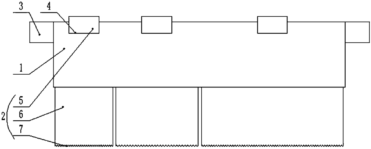
[0027] Such as Figure 1-4 As shown, a new type of zinc melting furnace includes an outer frame 1 and several inner furnaces 2. The outer frame 1 is a rectangular frame composed of four side walls, front, rear, left, and right. The left and right sides of the outer frame 1 Furnace lugs 3 are provided on the side walls of the outer furnace frame 1, and several groups of relative card slots 4 are provided on the side walls of the front and rear sides of the outer furnace frame 1;

[0028] The inner furnace 2 includes a furnace body 6, a bottom plate 7 and a block 5, the bottom plate 7 is arranged on the bottom of the furnace body 6, the block 5 is relatively arranged on the side walls of the front and rear sides of the furnace body 6, and the inner furnace hearth 2 and the outer hob 1 are clamped together through the clamping block 5 arranged in the clamping groove 4 . Both the outer frame 1 and the inner furnace 2 are made of steel plates.

[0029] The interior of the outer g...

Embodiment 2

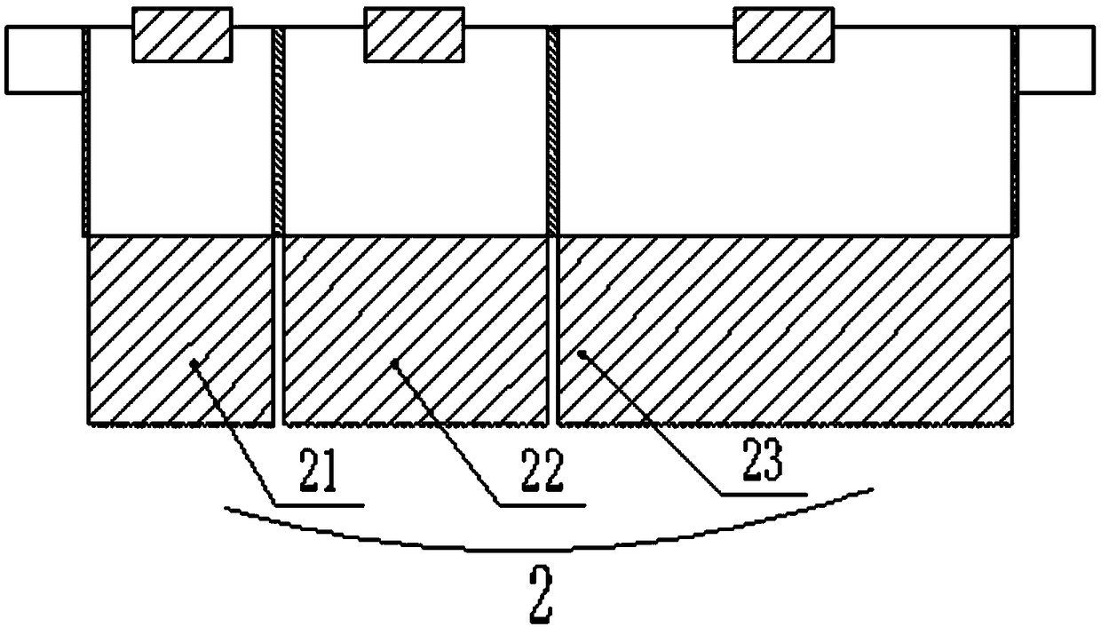
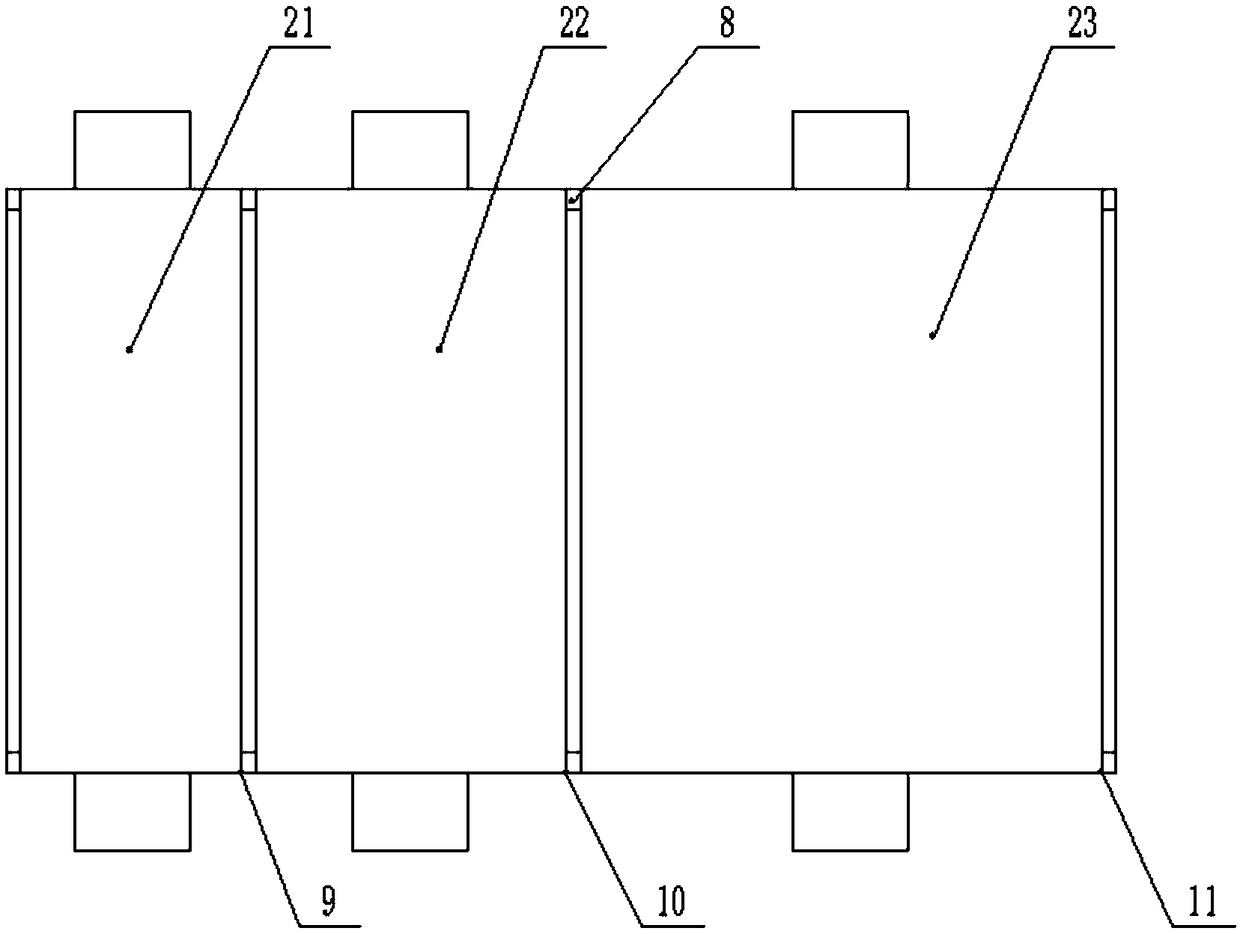
[0035] Such as Figure 1-4 As shown, this implementation is further optimized on the basis of Embodiment 1. This embodiment focuses on the improvements compared with Embodiment 1, and the similarities will not be repeated. In this embodiment, the inner furnace 2 Divided into the first inner furnace 21 , the second inner furnace 22 and the third inner furnace 23 , the volumes in the first inner furnace 21 , the second inner furnace 22 and the third inner furnace 23 increase sequentially. The inner furnace 2 with different volumes can make the amount and mode of molten zinc more flexible in the actual production process.


PUM


Abstract

The invention discloses a novel zinc melting furnace and belongs to the technical field of metal smelting. The problems that when a small number of zinc blocks are heated in an existing zinc melting furnace, heating time is long, and energy consumption needed by zinc block melting is high are solved. The novel zinc melting furnace comprises an outer furnace frame and a plurality of inner hearths.The outer furnace frame is a rectangular frame composed by front, rear, left and right side walls. The side walls of the left and right sides of the outer furnace frame are each provided with a furnace lug. The side walls of the front and rear sides of the outer furnace frame are each provided with multiple sets of oppositely formed clamping grooves. Each inner hearth comprises a furnace body, a bottom plate and clamping blocks, wherein the bottom plate is arranged at the bottom of the furnace body, the clamping blocks are arranged on the side walls of the front side and the rear side of the furnace body oppositely, and the inner hearth and the outer furnace frame are arranged in the clamping grooves and are clamped together through the clamping blocks.

Description

technical field [0001] The invention relates to the technical field of metal melting devices, in particular to a novel zinc melting furnace. Background technique [0002] The traditional zinc melting process often uses an externally heated hot-melt zinc block. Usually, the lead block is placed in the zinc melting furnace, and the combustion of natural gas, fuel oil or industrial coal is used as the heat source for melting the zinc block at the bottom of the furnace. The existing zinc melting furnace has a whole cavity. In the actual use process, the zinc block often does not cover the entire bottom of the furnace, and sometimes only a small amount of zinc block needs to be melted, which cannot be melted at all. Covering the bottom of the furnace, the zinc block may shake on the bottom of the furnace during the transfer of the zinc melting furnace, resulting in unclear position of the zinc block at the bottom of the furnace when heating, and the entire bottom of the furnace n...

Claims


Application Information

Patent Timeline
Patent Type & Authority Applications(China)
IPC IPC(8): F27B14/08F27D1/00
Inventor 张德彬
Owner CHENGDU JUNSHUO RUIZHI INFORMATION TECH CO LTD
Learn More