Coding unit (CU) division method applied to high efficiency video coding (HEVC)

A technology for encoding frame and depth, applied in the field of video encoding, can solve the problems of slow encoding speed and high computational complexity of HEVC encoding, and achieve the effect of improving encoding speed, realizing CU division, and achieving obvious acceleration effect.

Inactive Publication Date: 2018-10-26
HARBIN INST OF TECH
View PDF2 Cites 11 Cited by
  • Summary
  • Abstract
  • Description
  • Claims
  • Application Information

AI Technical Summary

Problems solved by technology

[0013] The purpose of the present invention is to propose a CU partition method for HEVC in order to solve the problems of high computational complexity and slow coding speed of existing HEVC coding

Method used


Image

  • Coding unit (CU) division method applied to high efficiency video coding (HEVC)
  • Coding unit (CU) division method applied to high efficiency video coding (HEVC)
  • Coding unit (CU) division method applied to high efficiency video coding (HEVC)

Examples


specific Embodiment approach 1

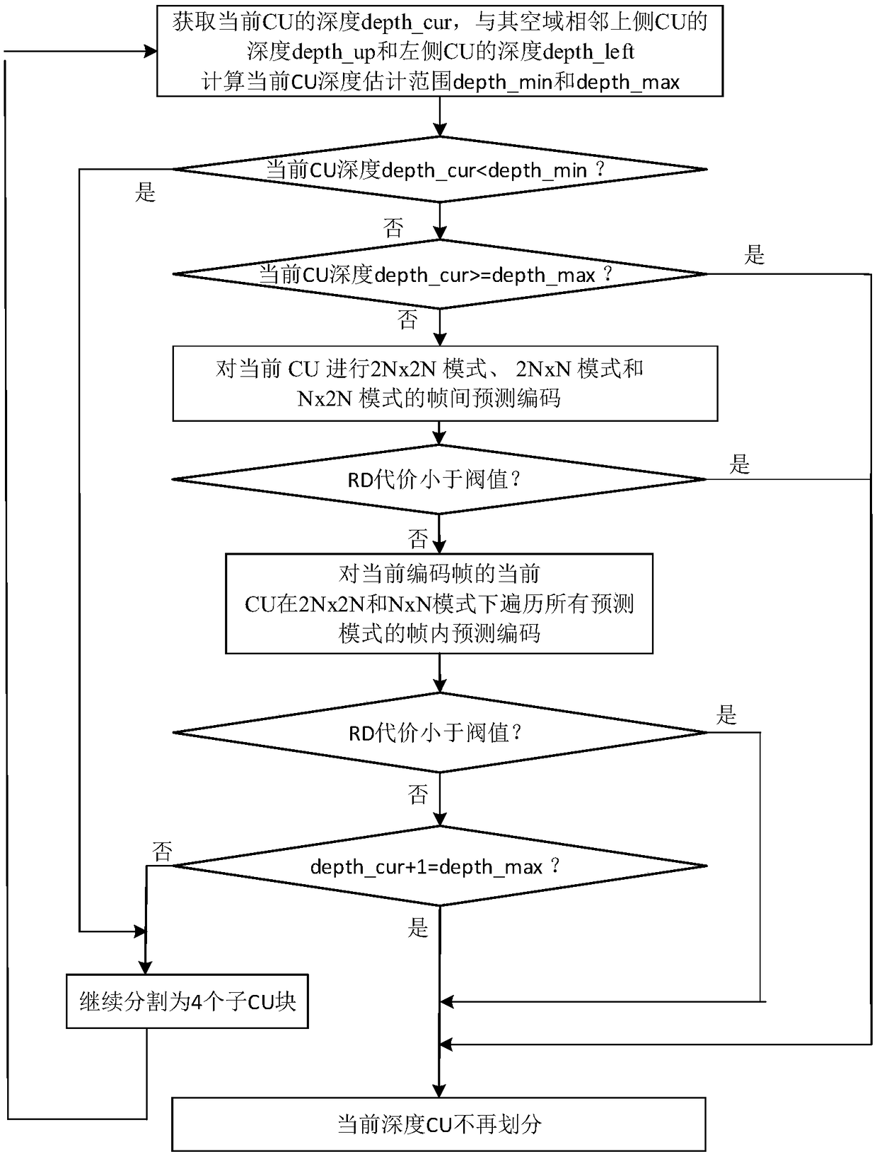
[0039] Specific implementation mode one: combine figure 1 Describe this embodiment, the specific process of a CU division method for HEVC in this embodiment is:

[0040] Step 1. The size of the current CU of the current coded frame is 2Nx2N, obtain the depth_cur of the current CU of the current coded frame, and obtain the space adjacent to the current CU of the current coded frame (only consider the upper and left sides of the same frame) The depth of the side CU and the left CU, so as to estimate the current CU depth minimum depth_min and maximum depth_max of the current coded frame;

[0041] The left and upper CUs of a CU refer to the left and upper CUs immediately adjacent to the upper left corner of the CU (such as Figure 7 shown).

[0042] That is, |depth_cur-depth_up|≤1 and |depth_cur-depth_left|≤1;

[0043] In this formula, the depths of the adjacent upper CU and left CU are known. By combining the two equations, the minimum depth_min and maximum depth_max of the cu...

specific Embodiment approach 2

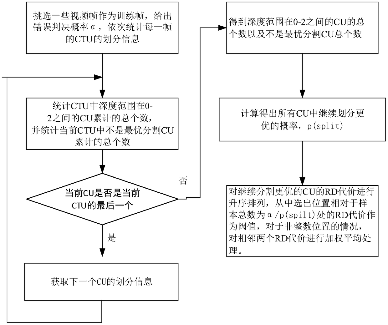
[0054] Embodiment 2: The difference between this embodiment and Embodiment 1 is that the specific calculation formula of the rate-distortion cost in the steps 2 and 3 is as follows:

[0055] J(s,c,QP,λ m )=SSD(s,c)+λ m B(s,c,QP)

[0056] Among them, J is the rate-distortion cost, λ m Represents the Lagrangian multiplier, QP represents the quantization coefficient, B is the number of bits required for encoding, s is the original CU, c is the reconstructed CU obtained by performing inter-frame prediction or intra-frame prediction on the original CU, SSD(s,c ) represents the difference sum of squares of s and c;

[0057] The bit rate B required for encoding is obtained by quantizing and encoding the prediction residuals of the original CUs and the reconstructed CUc by the HEVC encoder.

[0058] By quantizing and encoding the residuals of s and c, the number of bits is obtained as B(s,c,QP), and the size of QP affects B(s,c,QP);

[0059] The specific calculation method of SSD...

specific Embodiment approach 3

[0063] Specific implementation mode three: combination figure 2 This embodiment is described. The difference between this embodiment and the first or second embodiment is that the quantization coefficient QP takes an integer between 0 and 51 (only one QP value is taken each time).

[0064] Other steps and parameters are the same as those in Embodiment 1 or Embodiment 2.


PUM


Abstract

The invention discloses a coding unit (CU) division method applied to high efficiency video coding (HEVC), and relates to a HEVC technology. The invention aims at solving the problem that the existingHEVC coding technology is high in computing complexity and slow in coding speed. The method comprises the steps of 1, if the depth of the current CU is less than a minimum depth, turning to the step5; if the depth of the current CU is more than or equal to the maximum depth, ending; and otherwise turning to the step 2; 2, performing interframe prediction coding of 2N*2N, 2N*N and N*2N modes on the current CU, computing rate-distortion cost, if the rate-distortion cost is less than a threshold, ending, and otherwise, turning to the step 3; 3, performing interframe prediction coding of 2N*2N and N*N modes , computing the rate-distortion cost, if the rate-distortion cost is less than a threshold, ending, and otherwise, turning to the step 4; 4, judging whether the current CU reaches the maximum depth, if yes, ending, and otherwise, turning to the step 5; and 5, continuously dividing the current CU into four N*N sub-CU with the same size, and turning to the step 1. The method provided bythe invention is applied to the field of HEVC.

Description

technical field [0001] The present invention relates to the technical field of video coding, in particular to the high-efficiency video coding technology HEVC (H.265). Background technique [0002] Glossary: [0003] HEVC: High Efficiency Video Coding, high-performance video coding [0004] CTU: coding tree unit, coding tree unit [0005] CU: Coding Unit, coding unit [0006] PU: Prediction Unit, prediction unit [0007] RD: Rate Distortion, rate distortion [0008] In recent years, with the development of computer technology and the Internet, digital video plays an increasingly important role in video communication, film and television entertainment, security monitoring, military exploration and other fields. However, information such as images and videos contains a large part of redundant information, and the value density is low. Direct storage will waste huge storage space. Therefore, high-efficiency video compression technology is a prerequisite for video applicati...

Claims


Application Information

Patent Timeline
Patent Type & Authority Applications(China)
IPC IPC(8): H04N19/119H04N19/147H04N19/159H04N19/172H04N19/96
CPCH04N19/119H04N19/147H04N19/159H04N19/172H04N19/96
Inventor 李卓明赵钰肖振健岑尧辉陈幸沙学军杨林森侯静
Owner HARBIN INST OF TECH
Why Eureka
Try Eureka