Forced frequency ignition system for internal combustion engines

An ignition system and internal combustion engine technology, applied in the field of ignition coils and fuel electric ignition devices, can solve the problems of small size, complex electronics, and low quality, and achieve the effects of preventing radio frequency interference, reducing erosion, and easy radio frequency shielding

Active Publication Date: 2019-06-11
MARSHALL ELECTRIC
View PDF12 Cites 0 Cited by
  • Summary
  • Abstract
  • Description
  • Claims
  • Application Information

AI Technical Summary

Problems solved by technology

However, the method of extending the arc presents problems for the end user
First, the mechanism is actually electronically complex because multiple control mechanisms must exist in the form of two independent arc mechanisms
Second, no method is given for automatically sustaining the arc under repeated interruption conditions
Also, these mechanisms do not necessarily provide a low quality and small size single functional block unit that contains all the necessary functions

Method used


Image

  • Forced frequency ignition system for internal combustion engines
  • Forced frequency ignition system for internal combustion engines
  • Forced frequency ignition system for internal combustion engines

Examples


Embodiment Construction

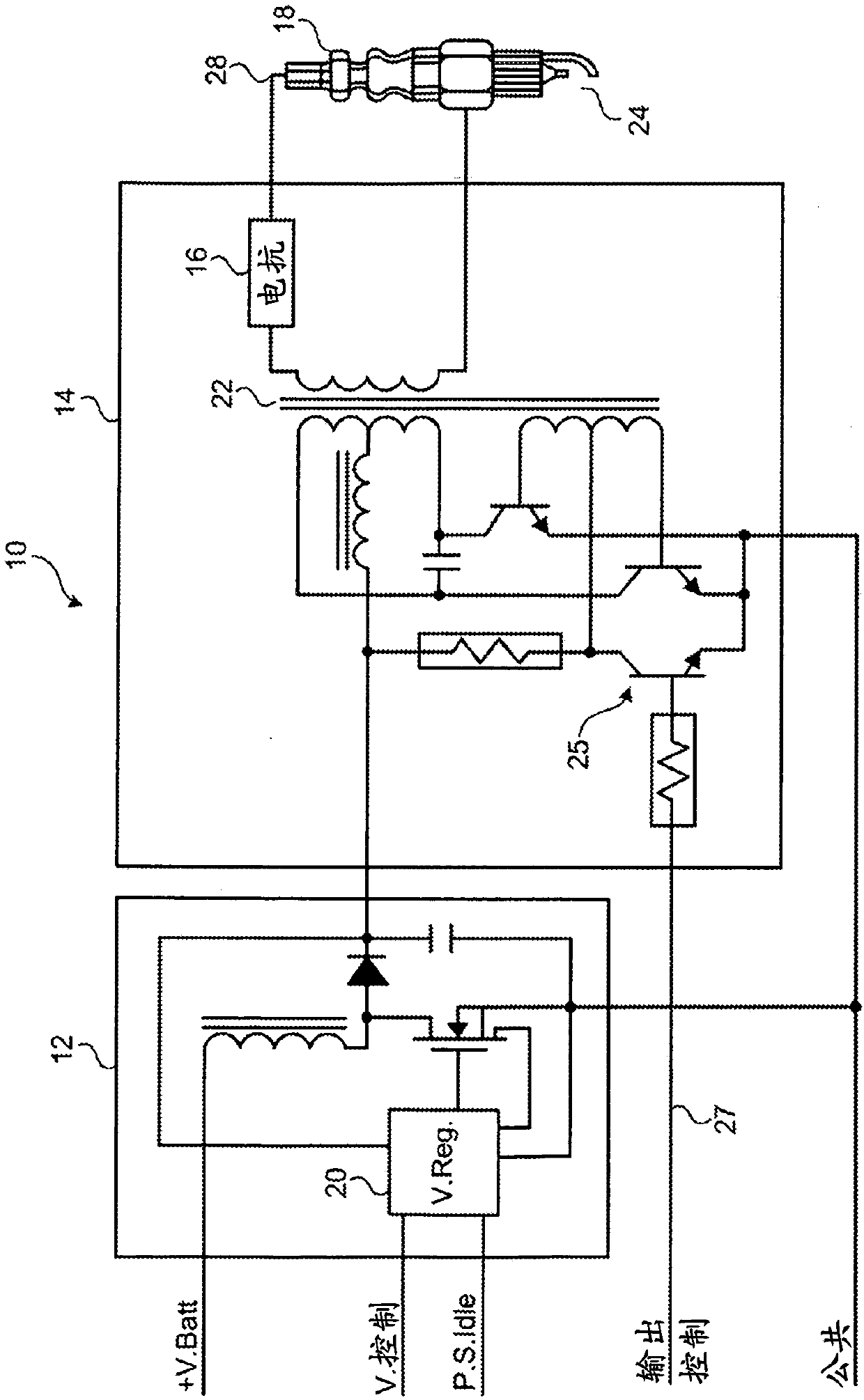
[0040] refer to figure 1 , which shows an ignition system 10 according to a preferred embodiment of the present invention. Ignition system 10 includes a pair of functional groups. The first functional group 12 is a power boost voltage regulator circuit. The second functional group 14 is the output section. The second functional group 14 produces a high voltage DC output which is current limited by the ballast reactance 16 . Functional groups 12 and 14 cooperate to properly ignite spark plug 18 . Functional group 12 is an input power boost voltage regulator. Functional group 12 provides feedback controlled regulated DC power to a second functional group 14 to allow the invention to be deployed in engine systems with varying input DC power voltages without adjustment. The input power boost voltage regulator 12 may additionally incorporate suitable means when appropriate to reduce the output voltage and enter an idle mode to reduce the overall module current drawn from the e...


PUM


Abstract

An ignition system (10) for an internal combustion engine has a power supply, a transformer (22) having first and second primary windings (32 and 33) and a secondary winding (30), extending from the secondary winding and adapted to A connector for terminal connection of a spark plug (18) of an internal combustion engine, and an electronic ignition timing circuit (42) cooperating with a transformer to activate and deactivate voltage to the first and second primary windings. The first and second primary windings are connected to the power supply such that the transformer produces an AC voltage output from the secondary windings between 1 kHz and 100 kHz and at a voltage of at least 20 kV. A forced push-pull inverter (82) works in conjunction with an electronic ignition timing circuit to fix the frequency of the voltage to the first and second primary windings.

Description

technical field [0001] The present invention relates to internal combustion engines. More specifically, the present invention relates to electrical ignition devices for igniting fuel within internal combustion engines. More specifically, the present invention relates to ignition coils for applying an alternating voltage to ignite a spark plug in an internal combustion engine. Background technique [0002] Most internal combustion engines have some type of ignition circuit to create a spark inside the cylinder. The spark causes the fuel in the cylinder to burn to drive the piston and the attached crankshaft. Typically, an engine includes a plurality of permanently mounted magnets mounted on a flywheel of the engine and a charging coil mounted on the engine casing near the flywheel. As the flywheel spins, the magnets pass over the charging coils. A voltage is thereby generated at the charging coil and used to charge the high-voltage capacitor. The high voltage charge on t...

Claims


Application Information

Patent Timeline
Patent Type & Authority Patents(China)
IPC IPC(8): F02P3/00F02P3/01F02P3/08F02P3/045F02P9/00F02P15/10
CPCH01T13/44F02P3/01F02P15/10H01T13/04F02P9/002F02P3/0435
Inventor T·C·玛尔斯S·P·巴洛
Owner MARSHALL ELECTRIC
Why Eureka
Try Eureka