Novel multifunctional three-dimensional scanner

A scanner and multi-function technology, applied in the field of 3D scanners, can solve the problems of affecting the use effect, unable to charge anytime and anywhere, wasting time, etc., to achieve the effect of convenient mobile use, avoiding timely use, and reducing weight

Inactive Publication Date: 2018-10-30
朱国志
View PDF0 Cites 1 Cited by
  • Summary
  • Abstract
  • Description
  • Claims
  • Application Information

AI Technical Summary

Problems solved by technology

[0002] A 3D scanner is used to obtain the 3D coordinates of the outer surface of the object and the 3D digital model of the object. However, with the development of science and technology, people's requirements for the 3D scanner are getting higher and higher, which makes the traditional 3D scanner unable to meet the requirements. People need a 3D scanner with more diverse functions and convenient use; the existing 3D scanners have certain disadvantages in use. First of all, the existing 3D scanners cannot timely emit damaged cameras and lasers Disassembly, replacement and repair of the scanner will affect the normal use of the 3D scanner. At the same time, it cannot be used alone. Secondly, it cannot be charged anytime and anywhere. When there is no power, it is necessary to find a designated place to charge and waste time. The hardness of the original casing is very good at the same time to reduce the weight. The existing 3D scanner is too heavy, which affects the use effect and has a certain impact on people's use process. Therefore, we propose a new multi-functional 3D scanner instrument

Method used


Image

  • Novel multifunctional three-dimensional scanner
  • Novel multifunctional three-dimensional scanner
  • Novel multifunctional three-dimensional scanner

Examples


Embodiment Construction

[0018] In order to make the technical means, creative features, objectives and effects achieved by the present invention easy to understand, the present invention will be further explained below in conjunction with specific embodiments.

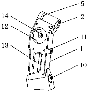
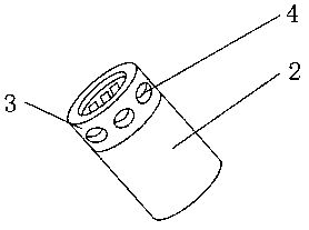
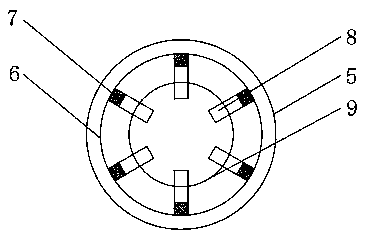
[0019] Such as Figure 1-5 As shown, a new type of multifunctional three-dimensional scanner includes a scanner main body 1, the inner top outer surface of the scanner main body 1 is provided with a No. 1 camera 2 near the front end position, and the rear end outer surface of the No. 1 camera 2 is fixedly installed Connecting shaft 3, the outer surface of the connecting shaft 3 is provided with a pin groove 4, the top outer surface of the scanner main body 1 is provided with a connecting ring 5 near the rear end, and the connecting ring 5 is provided with an inner ring 6, and the inner ring 6 An electromagnetic plate 7 is fixedly installed on the inner surface, and a movable pin 8 is movably installed above the electromagnetic plate 7, an inner ...


PUM


Abstract

The invention discloses a novel multifunctional three-dimensional scanner which comprises a scanner main body, wherein a camera I is arranged at the position, which is close to the front end, of the outer surface of the top end inside the scanner main body; and a connecting shaft is fixedly connected to the outer surface of the rear end of the camera I. The novel multifunctional three-dimensionalscanner disclosed by the invention is provided with a connecting ring, a power generation motor and a honeycomb plate, so that the damaged camera and laser transmitter can be detached and replaced intime, and the condition that normal use of the three-dimensional scanner is influenced because the scanner cannot be repaired in time is avoided. Meanwhile, the three-dimensional scanner can be detached to be singly used according to needs and is more convenient, the condition that time is wasted because a specified site needs to be found for charging is avoided by virtue of manual power generation, and timely use of the three-dimensional scanner is avoided from being influenced. In addition, the weight can be well lightened while ensuring the original shell hardness, the scanner is convenientto move and use, the phenomenon that the using effect is influenced due to heavy equipment is avoided, and the scanner brings excellent application prospects.

Description

Technical field [0001] The invention relates to the field of scanners, in particular to a novel multifunctional three-dimensional scanner. Background technique [0002] The 3D scanner is a kind of 3D digitized model used to obtain the 3D coordinates of the outer surface of the object. However, with the development of science and technology, people have higher and higher requirements for the 3D scanner. As a result, the traditional 3D scanner can no longer meet the requirements. People’s demand for use requires a three-dimensional scanner with more diverse functions and easy to use; the existing three-dimensional scanners have certain drawbacks when they are used. First, the existing three-dimensional scanners cannot promptly emit damaged cameras and lasers. Disassembly, replacement and repair of the 3D scanner will affect the normal use of the 3D scanner. At the same time, it cannot be used alone. Secondly, it cannot be charged anytime and anywhere. When there is no battery, it i...

Claims


Application Information

Patent Timeline
Patent Type & Authority Applications(China)
IPC IPC(8): G01B11/00G01C3/00H02J7/32
CPCG01B11/002G01C3/00H02J7/32Y02B40/00
Inventor 朱国志
Owner 朱国志
Why Eureka
Try Eureka