Double-air channel noise-reduction motor assembly and pet-cleaning machine

A technology with a noisy motor and dual air ducts is applied in the field of pet washing machines, which can solve problems such as high noise, and achieve the effects of reducing noise, increasing wall thickness, and improving heat dissipation.

Pending Publication Date: 2018-11-02
KINGCLEAN ELECTRIC
0 Cites 0 Cited by

AI-Extracted Technical Summary

Problems solved by technology

[0005] In view of this, the purpose of the present invention is to provide a dual air duct noise reduction motor assembly and a pet washing machine, which c...

Abstract

Provided is a double-air channel noise-reduction motor assembly. The double-air channel noise-reduction motor assembly comprises a motor and a motor inner cover. The motor is arranged in the interiorof the motor inner cover in a sealing manner through an inner separation and sealing ring. A motor outer cover is arranged coaxially outside the motor inner cover. The motor inner cover is fixed withthe motor outer cover through an elastic noise-reduction part. A noise reduction structure of a double-layer motor cover is formed by the motor inner cover and the motor outer cover. Therefore, the double-air channel noise-reduction motor assembly generates low noises. The heat radiation effect is improved. A user adopts a product more comfortably.

Application Domain

Technology Topic

Image

  • Double-air channel noise-reduction motor assembly and pet-cleaning machine

Examples

  • Experimental program(1)

Example Embodiment

[0023] Domestic pet washing machines that can have multiple functions such as bathing and drying are quietly emerging on the market. Because pets are easily frightened when bathing, this requires pet washing machines to have low noise effects, but the fundamentals are , The main source of noise is the motor components of the pet washing machine, so it is necessary to optimize the structure of the motor components to achieve the purpose of noise reduction.
[0024] The technical solutions of the present invention will be clearly and completely described below through specific implementations. Obviously, the described embodiments are only a part of the embodiments of the present invention, rather than all the embodiments. Based on the embodiments of the present invention, all other embodiments obtained by those of ordinary skill in the art without creative work shall fall within the protection scope of the present invention.
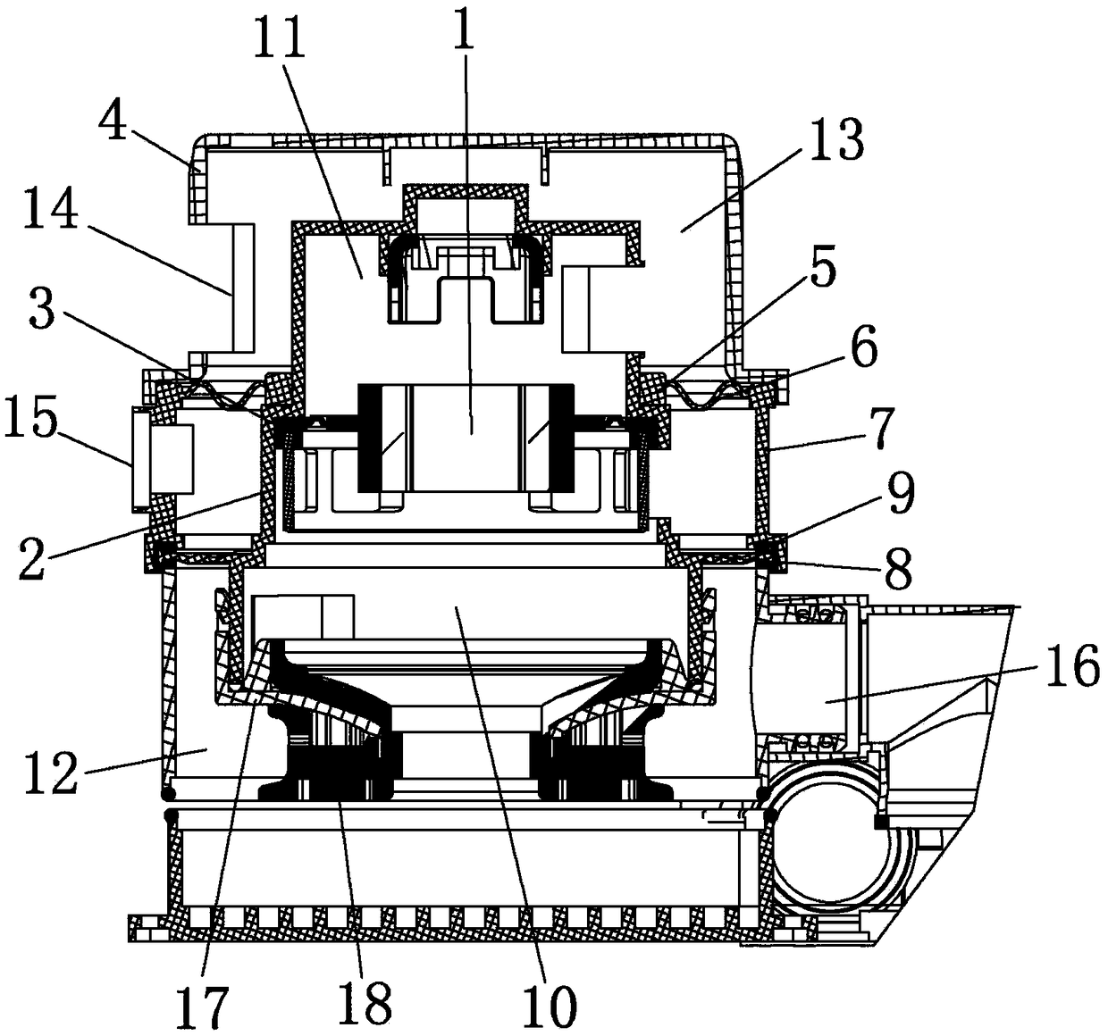
[0025] See figure 1 As shown, a dual air duct noise reduction motor assembly includes a motor 1 and a motor inner cover 2. The motor 1 is sealed and placed inside the motor inner cover 2 through an inner partition sealing ring 3, so that the motor 1 and the motor inner cover 2 are integrated The structure is convenient for later assembly. A motor outer cover 4 is also coaxially arranged outside the motor inner cover 2, and the motor inner cover 2 is fixed to the motor outer cover 4 by an elastic noise reduction component, so that the motor inner cover 2 and the motor outer cover 4 form a double-layer motor cover noise reduction structure.
[0026] Specifically, the noise reduction component includes a clamp 5, a wave-shaped elastic ring 6 and an annular sealing buffer sleeve 7. In order to reduce the processing steps, it is preferable to integrally form the clamp 5, the wave-shaped elastic ring 6 and the annular sealing buffer sleeve 7.
[0027] The clamp 5 is sealed and sleeved on the outer side wall of the motor inner cover 2, the annular sealing buffer sleeve 7 is kept in sealing abutment with the inner side wall of the motor outer cover 4, and the wave-shaped elastic ring 6 and the motor inner cover 2 are arranged coaxially and wavy. One end of the elastic ring 6 is connected with the clamp 5 to be integrally formed, and the other end is connected with the upper end of the annular sealing buffer sleeve 7, and the vibration reduction direction of the noise reduction component is parallel to the vibration direction of the motor inner cover. When the motor is running, a large vibration will be generated. The vibration is transmitted to the noise reduction component through the inner cover 2 of the motor, and the wave-shaped elastic ring 6 in the noise-reducing part can be made of plastic parts, so the wave-shaped elastic ring 6 is due to its The shape and material will be deformed as the motor vibrates, so that the motor 1 and the motor inner cover 2 can move up and down with small amplitude along the motor inner cover 2 axis, thereby achieving the first-stage vibration and noise reduction purpose.
[0028] A partition plate 8 extends from the outer side wall of the motor inner cover 2 and is connected to the lower end of the annular sealing buffer sleeve 7 in a sealed manner. An outer partition sealing ring 9 is provided at the joint between the two. The outer partition sealing ring 9 is U-shaped and the outer partition is sealed. The inner concave part of the ring 9 is clamped with the partition plate 8, and the outer part of the outer partition sealing ring 9 and the lower end part of the annular sealing buffer sleeve 7 are kept sealed and fixed. The vibration of the motor 1 and the motor inner cover 2 can be slow-released and offset along the circuit of the partition plate 8, the wave-shaped elastic ring 6, the annular sealing buffer sleeve 7, and the side wall of the motor inner cover 2 to achieve the second level of vibration reduction Noisy purpose.
[0029] Furthermore, the inner space of the motor inner cover 2 is divided by the plane where the partition plate 8 is located to form an inner main air duct 10 and an inner heat dissipation air duct 11, and the inner space of the motor outer cover 4 is divided by the partition plate 8 to form an outer main air The duct 12 and the outer heat dissipation air duct 13, the inner main air duct 10 and the inner heat dissipation air duct 11 are correspondingly connected with the outer main air duct 12 and the outer heat dissipation air duct 13. The side wall of the motor outer cover 4 is provided with a heat dissipation air inlet 14 and a heat dissipation air outlet 15 communicating with the outer heat dissipation air duct 13, and a motor air outlet 16 communicating with the outer main air duct 12. The motor inner cover 2 is in front of the motor 1. The lower air inlet, that is, the air inlet of the inner main air duct 10, is provided with an inner motor cover 17 and sealed and fixed by an air duct sealing ring 18.
[0030] The outside air enters the outer main air duct 12 of the motor outer cover 4 from the air inlet of the motor 1 through the inner main air duct 10 of the motor inner cover 2 and finally is discharged from the motor air outlet 16 to achieve the effect of motor suction. The outside cold air enters the heat dissipation air inlet 14 of the motor outer cover 4, enters the inner heat dissipation air duct 11 of the motor inner cover 2 through the outer heat dissipation air duct 13 to dissipate the motor 1, and then is discharged from the inner heat dissipation air duct 11 to the outer heat dissipation. The air duct 13 is finally discharged from the heat dissipation air outlet 15 to achieve the effect of heat dissipation of the motor. Compared with the existing motor, the present invention uses a double-layer motor cover noise reduction structure to extend the path of the main air duct and the heat dissipation air duct, and achieves the third-stage vibration and noise reduction purpose while also improving the heat dissipation effect. .
[0031] Finally, due to the double-layer motor cover noise reduction structure of the motor inner cover 2 and the motor outer cover 4, the wall thickness of the motor assembly is further increased, and the working noise is effectively reduced, which can be regarded as achieving the fourth level of vibration and noise reduction.
[0032] The invention provides a dual-air duct noise reduction motor assembly and a pet washing machine, which solves the problem of relatively large noise of the existing dual-air duct motor assembly, improves the heat dissipation effect, and enhances the product comfort.
[0033] The foregoing description of the disclosed embodiments enables those skilled in the art to implement or use the present invention. Various modifications to these embodiments will be obvious to those skilled in the art, and the general principles defined in this document can be implemented in other embodiments without departing from the spirit or scope of the present invention. Therefore, the present invention will not be limited to the embodiments shown in this document, but should conform to the widest scope consistent with the principles and novel features disclosed in this document.

PUM

no PUM

Description & Claims & Application Information

We can also present the details of the Description, Claims and Application information to help users get a comprehensive understanding of the technical details of the patent, such as background art, summary of invention, brief description of drawings, description of embodiments, and other original content. On the other hand, users can also determine the specific scope of protection of the technology through the list of claims; as well as understand the changes in the life cycle of the technology with the presentation of the patent timeline. Login to view more.

Similar technology patents

Schottky barrier diode

Owner:MITSUBISHI ELECTRIC CORP

Classification and recommendation of technical efficacy words

  • Reduce noise
  • Increase wall thickness

Microcircuits for small engines

ActiveUS20070177976A1Increase wall thicknessEngine manufactureEngine fuctionsSmall engineTurbine
Owner:RAYTHEON TECH CORP

Microtitration plate

InactiveUS20050058578A1Low toleranceIncrease wall thicknessBioreactor/fermenter combinationsBiological substance pretreatmentsEngineeringOxygen
Owner:EPPENDORF AG

Balloon catheter having a balloon with a thickened wall portion

InactiveUS7011646B2Increase wall thicknessIncrease strength of balloonStentsBalloon catheterSecondary layerHigh intensity
Owner:ABBOTT CARDIOVASCULAR

Ribbed hose for milk extraction

ActiveUS20090217879A1More flexibility and bendabilityIncrease wall thicknessCathetersHeat exhanger conduitsEngineeringMechanical engineering
Owner:WEISEL BEVERLY SUE
Why Eureka
Try Eureka