Novel environment-friendly plate cutting device

A cutting device and an environment-friendly technology, which is applied in the field of new environment-friendly plate cutting devices, can solve the problems of bulky, difficult to move, labor-intensive and time-consuming, etc.

Active Publication Date: 2018-11-02
OUYANG FURUI JIANGSU WOOD IND CO LTD
View PDF6 Cites 10 Cited by
  • Summary
  • Abstract
  • Description
  • Claims
  • Application Information

AI Technical Summary

Problems solved by technology

These often emit various industrial dusts in the process of industrial production, which will damage the air environment of the workshop, endanger the health of the operators, damage the machinery and equipment in the workshop, and pollute the atmospheric environment and cause social public nuisance.
[0003] And plate cutting is a very common operation process in industrial production. The existing plate cutting device is heavy, and the worker needs to hold it all the time during the operation, which is labor-intensive and inefficient. Some effects are slowed down, but for long-term operation, it consumes a lot of labor and time, it is not easy to move, and it is laborious to carry. After cutting one plate, the speed when cutting another plate is slow

Method used


Image

  • Novel environment-friendly plate cutting device
  • Novel environment-friendly plate cutting device
  • Novel environment-friendly plate cutting device

Examples


Embodiment Construction

[0027] Below in conjunction with accompanying drawing and specific embodiment the present invention is described in further detail:

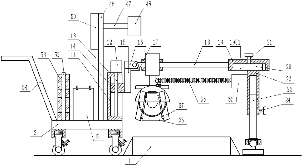
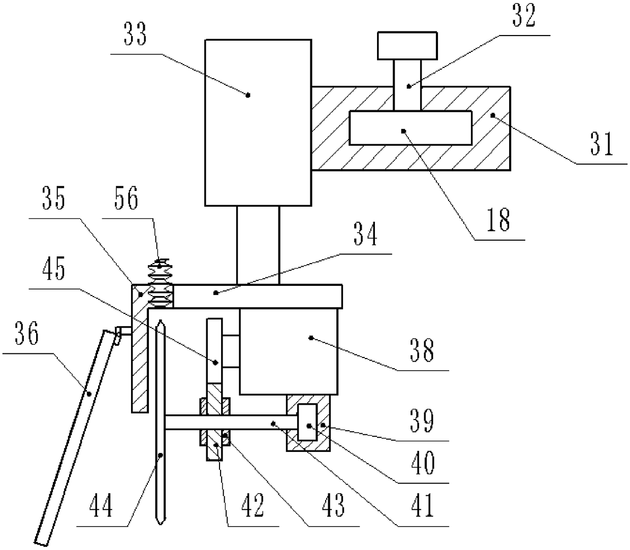
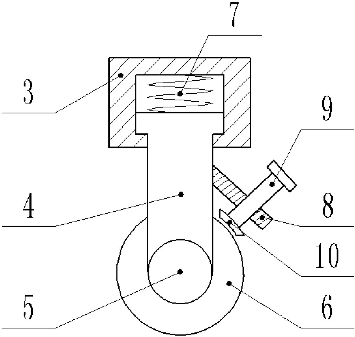
[0028] Such as Figure 1-Figure 7 As shown, a new environment-friendly plate cutting device includes a workbench 1 and a bottom plate 2 next to it. The lower end of the bottom plate 2 is fixed with a plurality of sleeves 3, and the lower end of the sleeve 3 is inserted with a vertical rod 4. , the lower end of the vertical bar 4 is rotatably connected with a wheel shaft 5, the wheel shaft 5 is covered with a roller 6 and fixed thereto, a spring 7 is fixed between the upper end of the vertical bar 4 and the upper wall of the sleeve 3, and the vertical bar 4 The side end is fixed with a slant plate 8, the angle between the lower end of the slant plate 8 and the vertical bar 4 is 45-50 degrees, the bolt 9 passes through the slant plate 8 and is threadedly connected with it, and the lower end of the bolt 9 is fixed There is a brake pad 10 above the...


PUM


Abstract

The invention discloses a novel environment-friendly plate cutting device. The novel environment-friendly plate cutting device comprises a workbench and a bottom plate located beside the workbench. Aplurality of sleeves are fixed to the lower end of the bottom plate. Vertical rods are inserted into the lower ends of the sleeves. Wheel shafts are rotationally connected with the lower ends of the vertical rods and sleeved with rolling wheels. The rolling wheels are fixed to the wheel shafts. Springs are fixed between the upper ends of the vertical rods and the upper walls of the sleeves. Oblique plates are fixed to the side ends of the vertical rods. Included angles are formed between the lower ends of the oblique plates and the vertical rods. Bolts penetrate through the oblique plates andare in threaded connection with the oblique plates. Brake pads located on the upper portion of the rolling wheels are fixed to the lower ends of the bolts. Blades are protected through protection plates, shielding plates and side shielding plates are stretched, the spark-splashing-prevention effect is achieved when the cutting blades cuts materials, the shielding plates and the side shielding plates are made from glass, the cutting state can be observed conveniently, a dust collector is adopted, dust produced in the cutting process can be adsorbed, and dust can be effectively prevented from affecting the operation environment.

Description

technical field [0001] The invention relates to the technical field of plate cutting, in particular to a novel environment-friendly plate cutting device. Background technique [0002] Industrial dust usually refers to dusty industrial waste gas or mechanical processes such as crushing, screening, conveying, blasting, etc. during the processing of solid materials. These often emit various industrial dusts in the process of industrial production, which will damage the air environment of the workshop, endanger the health of operators, damage the machinery and equipment in the workshop, and pollute the atmospheric environment and cause social public nuisance. [0003] And plate cutting is a very common operation process in industrial production. The existing plate cutting device is heavy, and the worker needs to hold it all the time during the operation, which is labor-intensive and inefficient. Some effects are slowed down, but for long-term operation, it consumes a lot of lab...

Claims


Application Information

Patent Timeline
Patent Type & Authority Applications(China)
IPC IPC(8): B23D15/06B23D19/08B23D47/08B23D47/12B23D33/00
CPCB23D15/06B23D19/08B23D33/00B23D47/08B23D47/12
Inventor 张明明
Owner OUYANG FURUI JIANGSU WOOD IND CO LTD
Why Eureka
Try Eureka