

Shrinkage fit and positioning tool for stator core and casing
A stator core and positioning tooling technology, which is applied in the mechanical field, can solve the problems that the relative position of the stator core and the casing cannot be guaranteed, the zero position of the position sensor is complicated to debug, and the level of automation cannot be satisfied, so as to improve the shrink fit Efficiency, the stability of the assembly process, and the effect of improving the coaxiality
- Summary
- Abstract
- Description
- Claims
- Application Information
AI Technical Summary
Problems solved by technology
Method used
Image

Examples
Embodiment 1
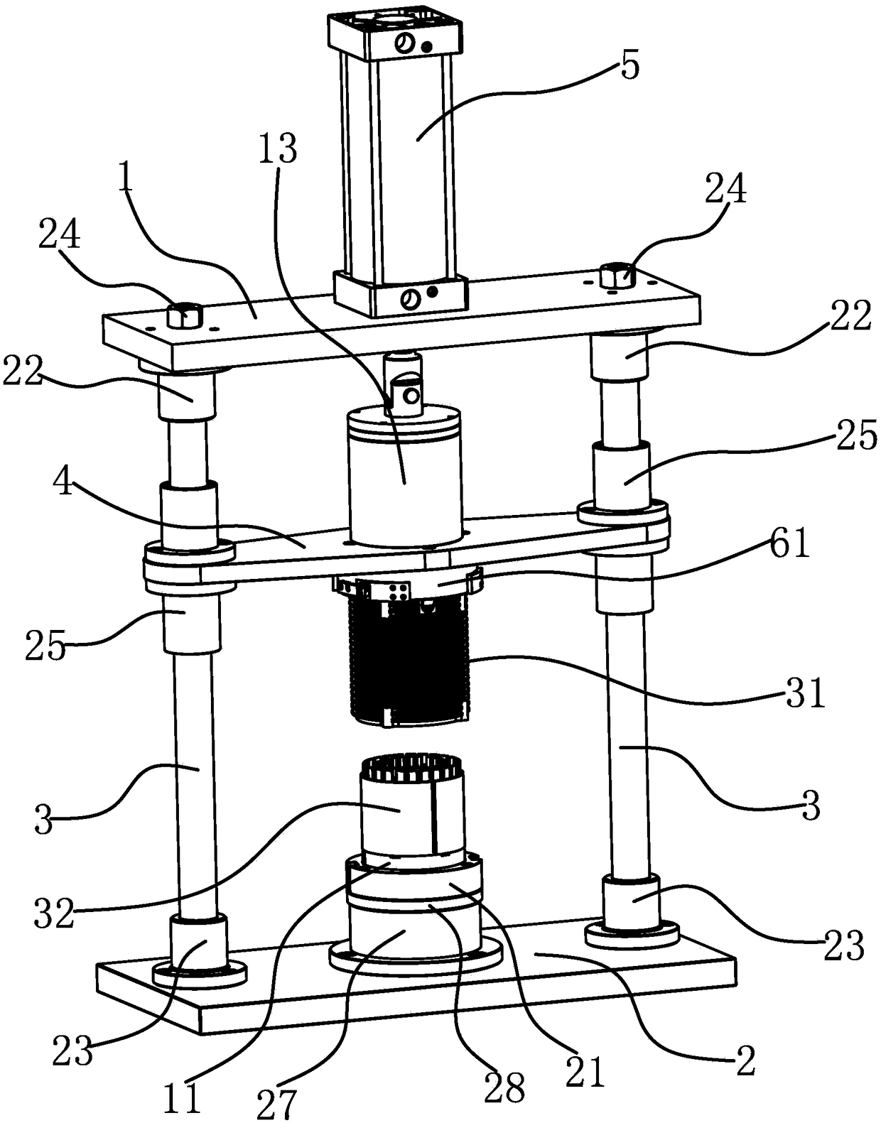
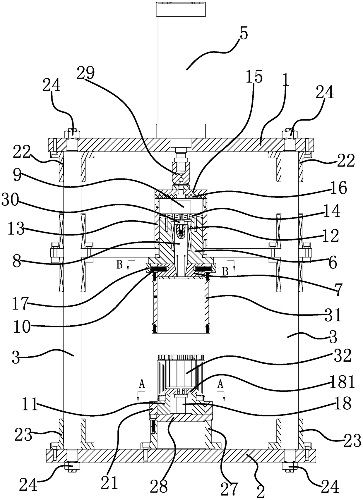
[0037] The shrink-fit positioning tool for the stator core and the casing includes an upper base 1, a lower base 2, a guide column, a support panel 4, a lifting drive source 5, a mounting seat 6, a positioning boss 61, and an inner support slider 7 , Telescopic guide rod 8, spring 10, positioning seat 11, limit structure and positioning structure.
[0038] Specifically, as figure 1 As shown, the number of columns 3 in this embodiment is two, and each column 3 has external threads at both ends, and the upper end of the column 3 passes through the fixing sleeve 22 on the upper base 1 and is fixed with the upper base 1 by a nut 24 , the lower end of the column 3 passes through the fixing sleeve 2 23 on the lower base 2 and is fixed with the lower base 2 by the nut 24, and the flange linear bearing 25 is fixed on the support panel 4, and the column 3 is respectively installed on the corresponding flange straight line On the bearing 25. The upper base 1 , the lower base 2 and the...
Embodiment 2
[0049] The technical solution in this embodiment is basically the same as the technical solution in Embodiment 1, the difference is that in this embodiment, the position-limiting structure includes a plurality of screw holes fixed on the mounting base 6 and matched with the screw holes of the casing 31. limit pin.
Embodiment 3
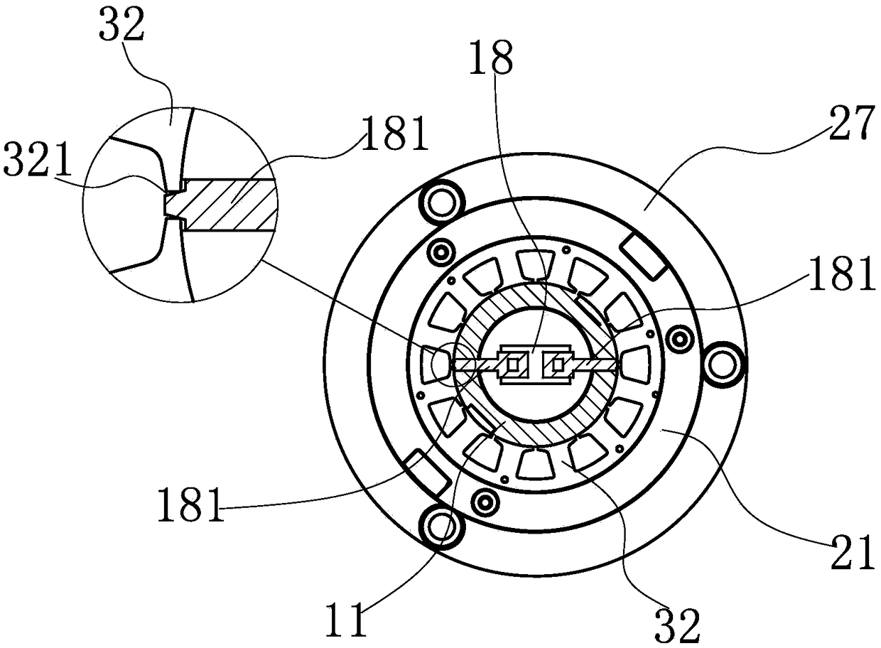
[0051] The technical solution in this embodiment is basically the same as the technical solution in Embodiment 1 and Embodiment 2, the difference is that in this embodiment, the positioning structure includes a convex body with elasticity, and the center of the upper end of the positioning seat 11 has a positioning The protrusion 111 of the seat 11 has a circular receiving groove 112 on the outer periphery of the protrusion 111 , and the protrusion is fixed on the outer surface of the protrusion 111 . When the stator core 32 is placed in the accommodating groove 112 , the stator core 32 is rotated in a circumferential direction, so that the convex body elastically deforms and snaps into the stator notch 321 , thereby realizing the positioning of the stator core 32 .
PUM
 Abstract
Description
Claims
Application Information