A kind of injection molding manipulator and injection molding method

A technology of manipulator and injection molding machine, applied in coating and other directions, can solve problems such as low work efficiency, and achieve the effect of improving work efficiency and quick operation

Active Publication Date: 2021-01-15
CIXI SANPEI MACHINE
View PDF5 Cites 0 Cited by
  • Summary
  • Abstract
  • Description
  • Claims
  • Application Information

AI Technical Summary

Problems solved by technology

[0004] Existing manipulators are generally used to take out injection-molded products, but when it is necessary to put parts into the mold and inject them together, the existing manipulators cannot form a joint with the injection molding machine from feeding, transferring, discharging to auxiliary parting. A set of complete, smooth and fast operations, so for the situation where the parts need to be put into the mold and injected together, the existing manipulator can only barely complete it in multiple disjointed actions, so the work efficiency is low

Method used


Image

  • A kind of injection molding manipulator and injection molding method
  • A kind of injection molding manipulator and injection molding method
  • A kind of injection molding manipulator and injection molding method

Examples


Embodiment 1

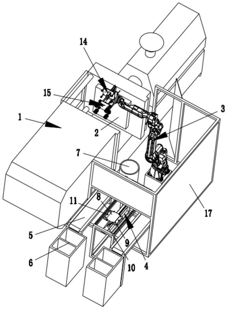
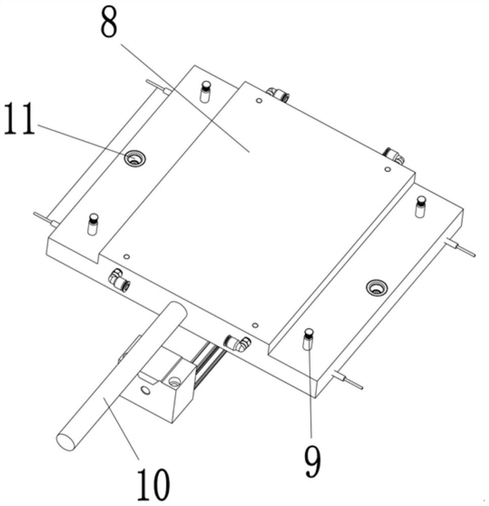
[0025] Embodiment one, such as Figure 1 to Figure 4 As shown, an injection molding manipulator includes an injection molding machine 1 and a mold 2 arranged on the injection molding machine 1, and a manipulator 3 corresponding to the mold 2 is provided on the side where the injection molding machine 1 operates, and the manipulator 3 One side of the frame 4 is provided with a material carrier 4, and the upper end of the material carrier 4 is provided with a shifting mechanism that can move the parts. A feeding belt 5 and a feeding motor are arranged between the shifting mechanism and the injection molding machine 1. A material detection workbench 6 is provided, and a defective product device box 7 is arranged between the shifting mechanism and the manipulator 3. The shifting mechanism includes a shifting support frame, and a slide rail is provided at the upper end of the shifting support frame. A displacement plate 8 is fitted on the rail, and a number of detection sensors are...

Embodiment 2

[0032] Embodiment 2, a divider assembly method, comprises the following steps:

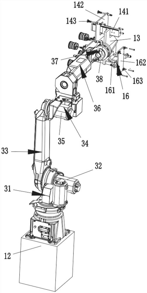
[0033] a. To place the parts, place the parts manually in the limiting concave hole 11 on the shift plate 8, and use the vacuum suction nozzle 143 to place and position the parts in the limiting concave hole 11, if the leakage occurs through the vacuum pressure and flow rate Monitoring and alarming, if it is put too much, it will run out of the limit concave hole 11;

[0034] b. To move the parts, the shifting plate 8 is controlled by the shifting cylinder 10 to move forward along the slide rail to the grasping position of the manipulator 3, and the manipulator 3 grabs the parts and moves to the direction of the mold 2. Specifically, the suction nozzle is controlled by the parts pick-and-place cylinder 141 143 moves down to contact with the parts, and then sucks the parts through the suction nozzle 143, and then the manipulator 3 controls the parts pick-and-place device 14 to move to the mold 2, a...


PUM


Abstract

The invention relates to the technical field of injection molding equipment, in particular to an injection molding manipulator and an injection molding method. The injection molding manipulator comprises a manipulator, a material bearing frame, a shifting mechanism, a material inspection worktable, a defective product device box, a shifting support frame, a shifting plate, a detection sensor, an error-proof detection shaft, a shifting cylinder, a part taking and placing device, a material taking device, an auxiliary parting device and a control device. The control device controls the shiftingmechanism to move a part to a position where the manipulator can grasp the part; then the part is moved toward a mold by the manipulator, and the material taking device takes out an injection molded finished product from the mold; then the part is implanted into the mold through the part taking and placing device; after that, defective products judged by an injection molding machine are put into the defective product box through the manipulator; and the injection molded finished product is placed on the worktable to be further inspected along a feeding belt by the material taking device. In this way, a complete set of smooth and quick operations of a product with parts placed in a mold for injection molding together can be achieved, so that the working efficiency is effectively improved.

Description

technical field [0001] The invention relates to the technical field of injection molding equipment, in particular to an injection molding manipulator and an injection molding method. Background technique [0002] With the development of computer and automation technology, manipulators are widely used in industrial production to replace human [0003] manual operation. In the existing field of injection molding, the role of the manipulator of the injection molding machine is to take out the injected product from the mold. The action of the manipulator requires high precision and reliable material removal. [0004] Existing manipulators are generally used to take out injection-molded products, but when it is necessary to put parts into the mold and inject them together, the existing manipulators cannot form a joint with the injection molding machine from feeding, transferring, discharging to auxiliary parting. A set of complete, smooth and fast operations, so for the situati...

Claims


Application Information

Patent Timeline
Patent Type & Authority Patents(China)
IPC IPC(8): B29C45/42B29C45/14B29C45/76
CPCB29C45/14008B29C45/4225B29C45/7686B29C2045/14049B29C2945/7629
Inventor 林双戴波李松伟
Owner CIXI SANPEI MACHINE
Why Eureka
Try Eureka