
Mobile waste carton compression equipment for logistics vehicle

A compression equipment, mobile technology, applied in the field of compression equipment, can solve the problems of garbage compression, occupying space, complicated operation, etc.

Inactive Publication Date: 2018-11-02
吴叶辉
View PDF7 Cites 3 Cited by
  • Summary
  • Abstract
  • Description
  • Claims
  • Application Information

AI Technical Summary

Problems solved by technology

[0005] In order to overcome the disadvantages of poor compression effect of existing compression equipment, the inability to compress garbage to the maximum volume, complicated operation, and space occupation, the technical problem of the present invention is to provide a kind of equipment that is easy to operate, has good compression effect, and can effectively use space. Mobile waste carton compression equipment for logistics vehicles

Method used


Image

  • Mobile waste carton compression equipment for logistics vehicle
  • Mobile waste carton compression equipment for logistics vehicle
  • Mobile waste carton compression equipment for logistics vehicle

Examples


Embodiment 1

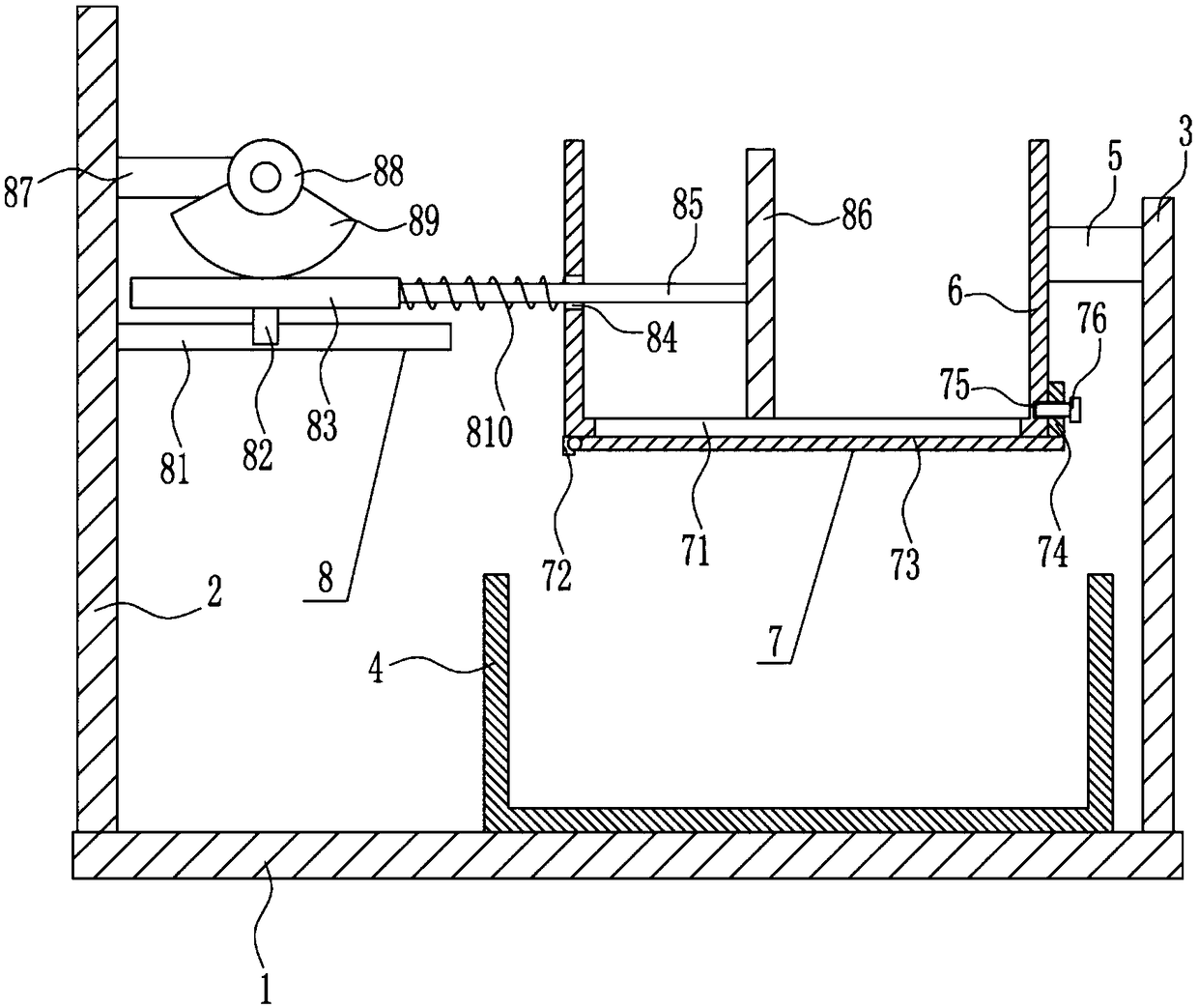
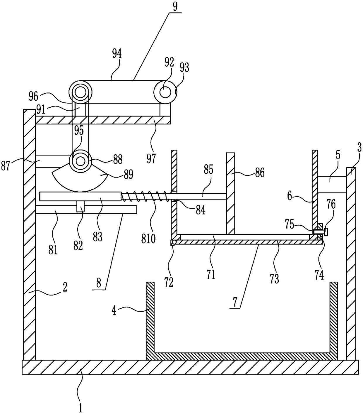
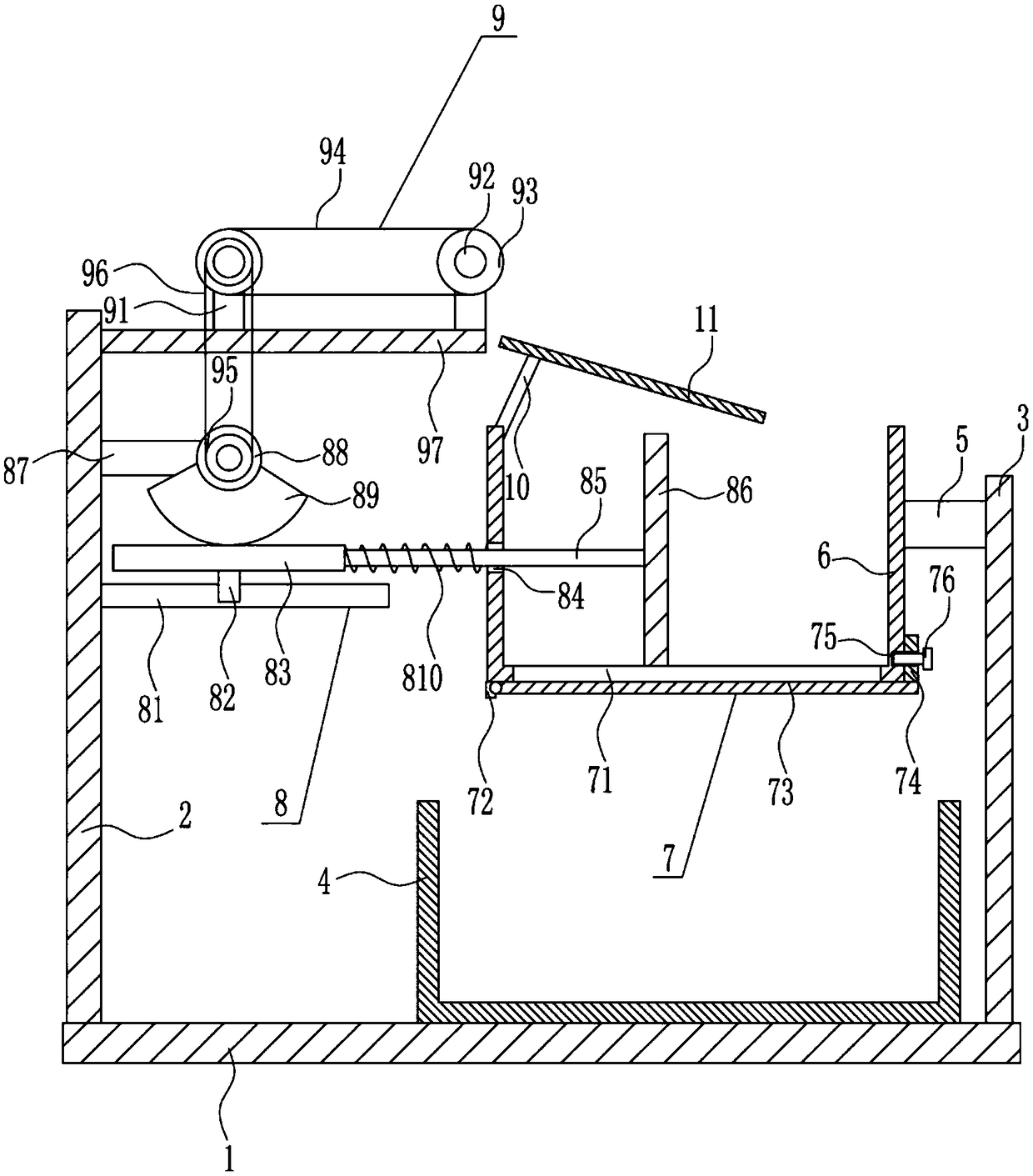
[0026] A mobile compression device for waste cartons for logistics vehicles, such as Figure 1-4 As shown, it includes a bottom plate 1, a left bracket 2, a right bracket 3, a collection box 4, a cross bar 5, an extrusion box 6, a feeding mechanism 7 and an extrusion mechanism 8, and the upper left part of the bottom plate 1 is fixedly connected with a left bracket 2. The upper right part of the bottom plate 1 is fixedly connected with the right bracket 3, the upper right part of the bottom plate 1 is provided with a collection box 4, the upper left side of the right bracket 3 is fixedly connected with a crossbar 5, and the left side of the crossbar 5 is provided with an extrusion box 6. The squeeze box 6 is located directly above the collection box 4, the bottom of the squeeze box 6 is provided with a feeding mechanism 7, and the upper part of the right side of the left bracket 2 is provided with an extrusion mechanism 8.

Embodiment 2

[0028] A mobile compression device for waste cartons for logistics vehicles, such as Figure 1-4 As shown, it includes a bottom plate 1, a left bracket 2, a right bracket 3, a collection box 4, a cross bar 5, an extrusion box 6, a feeding mechanism 7 and an extrusion mechanism 8, and the upper left part of the bottom plate 1 is fixedly connected with a left bracket 2. The upper right part of the bottom plate 1 is fixedly connected with the right bracket 3, the upper right part of the bottom plate 1 is provided with a collection box 4, the upper left side of the right bracket 3 is fixedly connected with a crossbar 5, and the left side of the crossbar 5 is provided with an extrusion box 6. The squeeze box 6 is located directly above the collection box 4, the bottom of the squeeze box 6 is provided with a feeding mechanism 7, and the upper part of the right side of the left bracket 2 is provided with an extrusion mechanism 8.

[0029] The blanking mechanism 7 includes a fixed blo...

Embodiment 3

[0031] A mobile compression device for waste cartons for logistics vehicles, such as Figure 1-4As shown, it includes a bottom plate 1, a left bracket 2, a right bracket 3, a collection box 4, a cross bar 5, an extrusion box 6, a feeding mechanism 7 and an extrusion mechanism 8, and the upper left part of the bottom plate 1 is fixedly connected with a left bracket 2. The upper right part of the bottom plate 1 is fixedly connected with the right bracket 3, the upper right part of the bottom plate 1 is provided with a collection box 4, the upper left side of the right bracket 3 is fixedly connected with a crossbar 5, and the left side of the crossbar 5 is provided with an extrusion box 6. The squeeze box 6 is located directly above the collection box 4, the bottom of the squeeze box 6 is provided with a feeding mechanism 7, and the upper part of the right side of the left bracket 2 is provided with an extrusion mechanism 8.

[0032] The blanking mechanism 7 includes a fixed bloc...


PUM


Abstract

The invention relates to a compression equipment , in particular to a mobile waste carton compression equipment for a logistics vehicle. According to the mobile waste carton compression equipment forthe logistics vehicle, the operation is simple and convenient, the compression effect is high, and the space can be effectively used. The mobile waste carton compression equipment for the logistics vehicle includes a bottom plate, a left bracket, a right bracket, a collection box, a transverse rod, a extrusion box and the like; the upper side of the bottom plate is fixedly connected with the leftbracket, the right part of the upper side of the bottom plate is fixedly connected with the right bracket, the collection box is arranged on the right part of the upper side of the bottom plate, the transverse rod is fixedly connected with the upper part of the left side of the right bracket, and the extrusion box is arranged on the left side of the transverse rod. According to the mobile waste carton compression equipment for the logistics vehicle, the cartons are extruded through an extrusion mechanism, then the extruded cartons drop into the collection box through a discharging mechanism, and then are transported through a conveying mechanism, the time spent by manual conveying is saved, and the effects that the operation is simple and convenient, the compression effect is high, and thespace can be effectively used are achieved.

Description

technical field [0001] The invention relates to a compression device, in particular to a mobile compression device for waste cartons used in logistics vehicles. Background technique [0002] Abandoned cartons refer to items that lose their original use value within a certain time and space range, and can be reused after recycling. [0003] Compression equipment is one of the main equipment to achieve garbage compression and volume reduction, and it is also the main processing equipment of the garbage transfer station. [0004] Waste cartons can be recycled, and they should be compressed after collection. At present, the compression equipment used by people is inefficient when compressing waste cartons, and the operation is a little more complicated. Moreover, the compression effect is not very good, the compression is not complete, and the maximum volume cannot be achieved. Therefore, there is an urgent need to develop a mobile waste carton compression equipment for logisti...

Claims


Application Information

Patent Timeline
Patent Type & Authority Applications(China)
IPC IPC(8): B65F9/00B65F3/14
CPCB65F3/14B65F9/00Y02W30/64
Inventor 吴叶辉
Owner 吴叶辉
Learn More