
Baffle tube material stirring swing arm device

A power plant and track technology, applied in the directions of transportation and packaging, conveyors, conveyor objects, etc., can solve the problems of many automation control points and heavy equipment maintenance workload, and achieve simple and reliable structure, easy equipment maintenance, and easy automation. effect achieved

Inactive Publication Date: 2018-11-02
XINXING HEBEI ENG & RES INC
View PDF6 Cites 5 Cited by
  • Summary
  • Abstract
  • Description
  • Claims
  • Application Information

AI Technical Summary

Problems solved by technology

Because this kind of shifting device is equipped with two sets of power, there are many automatic control points, and the workload of equipment maintenance is relatively large.

Method used


Image

  • Baffle tube material stirring swing arm device
  • Baffle tube material stirring swing arm device
  • Baffle tube material stirring swing arm device

Examples


Embodiment Construction

[0015] It should be noted that, in the case of no conflict, the embodiments of the present invention and the features in the embodiments can be combined with each other.

[0016] In describing the present invention, it should be understood that the terms "center", "longitudinal", "transverse", "upper", "lower", "front", "rear", "left", "right", " The orientations or positional relationships indicated by "vertical", "horizontal", "top", "bottom", "inner" and "outer" are based on the orientations or positional relationships shown in the drawings, and are only for the convenience of describing the present invention and Simplified descriptions, rather than indicating or implying that the device or element referred to must have a particular orientation, be constructed and operate in a particular orientation, and thus should not be construed as limiting the invention. In addition, the terms "first", "second", etc. are used for descriptive purposes only, and should not be understood ...


PUM


Abstract

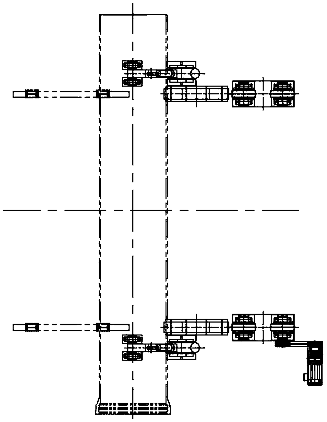
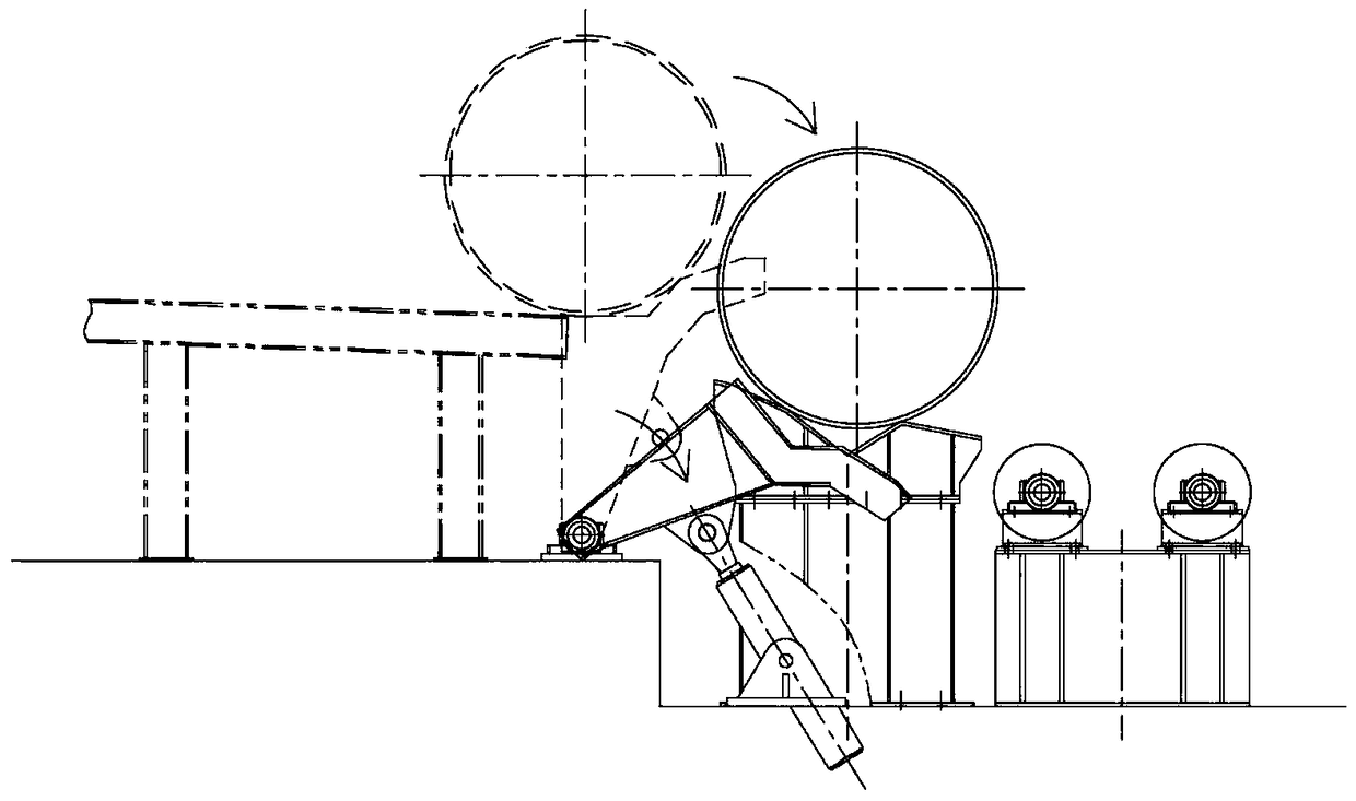
The invention discloses a baffle tube material stirring swing arm device. The device comprises a non-driving rail and a baffle stirring swing arm device, the baffle stirring swing arm device is arranged at the right end of the non-driving rail, a hydraulic cylinder is connected with the left side of the baffle stirring swing arm device, the hydraulic cylinder is connected with the ground through ahydraulic cylinder hinge supporting seat, a base is arranged on the right side of the baffle stirring arm device, a V-shaped supporting member is arranged on the base, a traction wheel group is arranged on the right side of the base, and a power device matched with the traction wheel group is arranged on the traction wheel group. The baffle tube material stirring swing arm device has a simple andreliable structure, automated achievement and equipment maintenance are easy, the non-driving rail in a buffering area is provided with tilting angle to help the baffle tube to stop at a tube receiving position of the baffle stirring swing arm device, and a single hydraulic cylinder is adopted to provide power.

Description

technical field [0001] The invention relates to the technical field of production of nodular cast iron pipes, in particular to a swing arm device for retaining pipes and pulling materials. Background technique [0002] In the production process of ductile iron pipes, in order to meet the specific production process requirements, the cast pipes temporarily stored in the buffer zone need to be moved to the next station for corresponding processing. Therefore, when the casting pipe enters and exits the station, it is necessary to arrange a shifting device or a transport vehicle to realize the movement of the casting pipe. In the station where slight impact is allowed, a dial device is usually used. Among the shifting devices commonly used in the production line, two sets of hydraulic cylinders are required for the coordinated operation of the shifting operation and the shifting operation. When the station is ready, the pipe retaining device acts to transport the buffer pipe w...

Claims


Application Information

Patent Timeline
Patent Type & Authority Applications(China)
IPC IPC(8): B65G47/88
CPCB65G47/8846B65G2201/0276
Inventor 习杰杜鹏远吴亮亮
Owner XINXING HEBEI ENG & RES INC
Learn More