Lamp tube forming mold

A technology for forming molds and lamps, applied in glass forming, glass reshaping, manufacturing tools, etc., can solve the problems of increasing lamp production costs, reducing production efficiency, and predicting high energy consumption, and saving preheating energy consumption , Improve work efficiency and high strength

Inactive Publication Date: 2018-11-02
南京合力电光源设备制造厂
View PDF1 Cites 0 Cited by
  • Summary
  • Abstract
  • Description
  • Claims
  • Application Information

AI Technical Summary

Problems solved by technology

In the actual lamp tube forming process, the mold needs to be preheated in advance before being sent into the lamp tube to make the temperature of the mold close to the temperature of the glass lamp tube, so as to prevent the glass lamp tube from bursting when it comes into contact with the mold with a large temperature difference. Some of them are solid moulds. It usually takes 1 hour to predict the mould. If the preheating time is too long, the expected energy consumption is too high, which increases the production cost of the lamp tube and reduces the production efficiency.

Method used


Image

  • Lamp tube forming mold
  • Lamp tube forming mold
  • Lamp tube forming mold

Examples


Embodiment 1

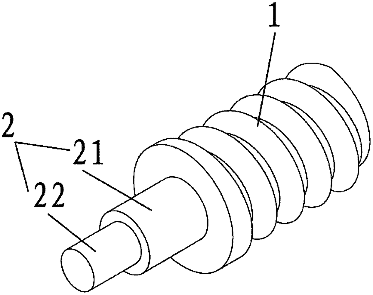
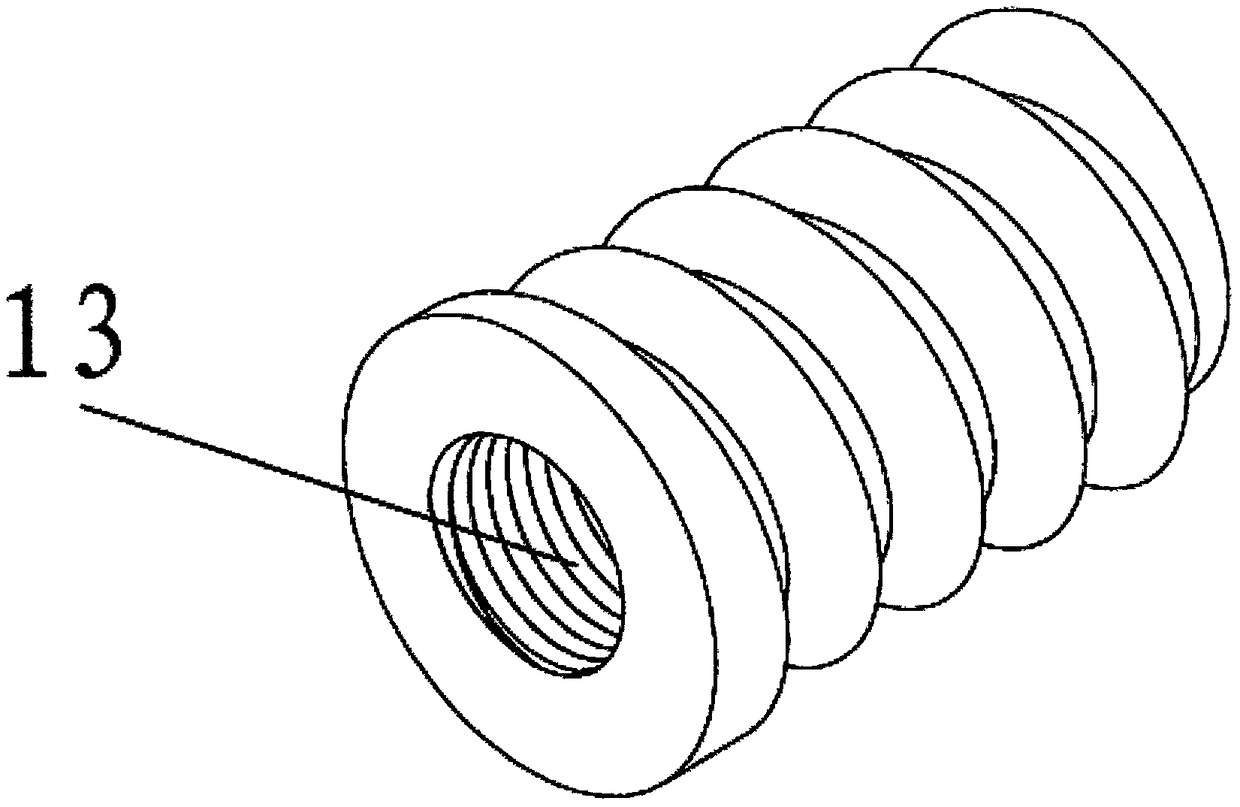
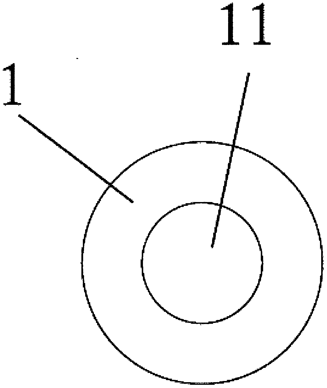
[0030] A lamp tube forming mold includes a mold main body 1 and a connecting shaft 2 arranged on the mold main body 1 for moving or rotating the mold main body 1, in which a cylindrical cavity 11 is provided. The connecting shaft 2 is detachably connected with the mold main body 1. The mold main body 1 is provided with two through holes 12 that allow the inside and outside of the cavity 11 to communicate with each other in air flow. The connecting shaft 2 and the through hole 12 are respectively arranged at both ends of the mold main body 1. The mold main body 1 is provided with a connecting port 13 with an internal thread, and the connecting shaft 2 is provided with an external thread adapted to the internal thread. The connecting shaft 2 is divided into a connecting section 21 that is close to and connected to the mold body 1 and has a larger diameter, and a transmission section 22 that is far from the mold body 1 and has a smaller diameter. The diameter of the cavity 11 is...

Embodiment 2

[0032] The difference from the foregoing embodiment is that there are four through holes, and the diameter of the cavity 11 is 3 / 4 of the diameter of the mold body. The diameter of the through hole 12 is 1 / 5 of the diameter of the cavity 11.

[0033] The cavity 11 provided in the mold reduces the material used for the mold and reduces the material cost, and the preheating time is shortened from 1 hour to 10-20 minutes, which improves work efficiency, saves preheating energy consumption and reduces costs .

[0034] The connecting shaft 2 and the mold main body 1 can be processed separately, which is convenient for processing. The connecting shaft 2 and the mold main body 1 can be replaced separately after being damaged, and only the connecting shaft 2 or the mold main body 1 can be produced separately according to the needs when the mold is produced, which reduces the replacement cost from both aspects. At the same time, different models of molds only need to replace the mold main...


PUM


Abstract

The invention belongs to the field of lamp tube manufacturing and specifically relates to a spiral lamp tube forming mold which comprises a mold main body and a connection shaft, wherein the connection shaft is arranged on the mold main body and is used for moving or rotating the mold main body, a cavity is arranged in the mold main body, the connection shaft and the mold main body are detachablyconnected, a through hole for air flows inside and outside the cavity to circulate is arranged on the mold main body, the connection shaft and the through hole are respectively arranged at the two ends of the mold main body, a connection opening with an internal thread is arranged on the mold main body, and an external thread matched with the internal thread is arranged on the connection shaft; the connection shaft is divided into a connection section and a transmission section, the connection section is close to and connected with the mold main body, the diameter of the connection section islarger, the transmission section is far from the mold main body, and the diameter of the transmission section is smaller. The mold is provided with the cavity, so that a used material of the mold is reduced, and material cost is reduced; furthermore, preheating time is shortened to 10 to 20 minutes from original 1 hour, and work efficiency is improved; meanwhile, preheating energy consumption is reduced, and cost is reduced.

Description

Technical field [0001] The invention belongs to the field of lamp tube manufacturing, and specifically relates to a spiral-shaped lamp tube forming mold. Background technique [0002] The existing forming molds used for manufacturing the spiral lamp tube are all solid molds, and the connecting shaft and the mold are integrally formed, which requires a lot of materials, high growth, and troublesome processing. In the actual tube forming process, the mold needs to be preheated in advance to make the mold temperature close to the temperature of the glass tube before sending it to the tube to prevent tube bursting when the glass tube is in contact with the mold with a large temperature difference. Some of these are solid molds, and it usually takes 1 hour to predict the mold. The preheating time is too long and the energy consumption is expected to be too high, which increases the production cost of the lamp and reduces the production efficiency. For example, in the molding device o...

Claims


Application Information

Patent Timeline
Patent Type & Authority Applications(China)
IPC IPC(8): C03B23/045
CPCC03B23/045Y02P40/57
Inventor 高国干
Owner 南京合力电光源设备制造厂
Why Eureka
Try Eureka