Novel special-shaped cushion strip suitable for winding around tubular heat exchanger

A winding tube type, heat exchanger technology, applied in the direction of heat exchanger shell, heat exchange equipment, lighting and heating equipment, etc., can solve the problems of heat exchange tube rupture, expansion of winding diameter, affecting heat exchange efficiency of heat exchanger, etc. , to avoid radial expansion and upward displacement

Active Publication Date: 2018-11-02
BC P INC CHINA NAT PETROLEUM CORP +1
View PDF5 Cites 2 Cited by
  • Summary
  • Abstract
  • Description
  • Claims
  • Application Information

AI Technical Summary

Problems solved by technology

[0005] like Figure 4 As shown, the existing special-shaped pads 1 used in the coiled tube heat exchanger all adopt arc-shaped grooves. During the manufacturing process of the heat exchanger, this special-shaped pad is convenient for the embedding of the spiral heat exchange tube 6, but In use, in the case of thermal expansion, the heat exchange tube will have an axial movement effect due to expansion. Due to the restriction of the arc-shaped groove, it will move along the curved surface of the arc-shaped groove, resulting in axial displacement components and radial displacements. As a result, the winding diameter of the heat exchange tubes in this layer becomes larger. When similar changes occur in each layer of heat exchange tubes, the total winding diameter of the tube bundle will be significantly enlarged, which will seriously affect the heat exchange efficiency of the heat exchanger.
In addition, when the heat exchanger expands and moves along the curved surface of the groove, the groove will also squeeze the heat exchange tube, forming a pressing force P between each other, resulting in local rupture of the heat exchange tube, thereby affecting the service life of the equipment

Method used


Image

  • Novel special-shaped cushion strip suitable for winding around tubular heat exchanger
  • Novel special-shaped cushion strip suitable for winding around tubular heat exchanger
  • Novel special-shaped cushion strip suitable for winding around tubular heat exchanger

Examples


Embodiment Construction

[0025] The present invention will be further described below in conjunction with the accompanying drawings.

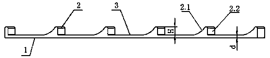
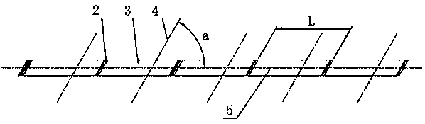
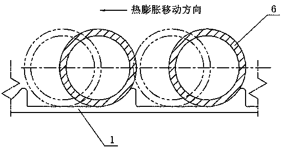
[0026] Such as Figure 1-3 As shown, the special-shaped gasket involved in the present invention includes a base 1, on the upper surface of the base 2, along the length direction, several grooves 3 are made according to the design requirements under the specific use, and between each groove 3 is Plate-shaped tooth-shaped protrusions 2, tooth-shaped protrusions 2 are parallel to each other and distributed at equal intervals, so that the axes 5 of each groove 3 are parallel to each other, and are used to place the involved tube body 6, for example, the heat exchanger of a wound heat exchanger. heat bundle.

[0027] The front side 2.1 of the tooth-shaped protrusion can adopt a circular arc surface or a similar cylindrical surface in the prior art, and the rear side 2.2 adopts a plane and is preferably perpendicular to the bottom plane of the groove. When installing, the ...


PUM


Abstract

The invention relates to a novel special-shaped cushion strip suitable for winding around a tubular heat exchanger. The cushion strip comprises a strip-shaped base, a plurality of tooth-shaped protrusions are distributed at equal intervals in the length direction of the upper surface of the base, the tooth-shaped protrusions are parallel to one another, grooves are formed between the adjacent tooth-shaped protrusions, and the bottom faces of the grooves are plane. The width of the grooves can be designed according to a use requirement and is adopted to the size of a tube body and the axial movement range of the tube body, when the tube body moves forward in the axial direction due to thermal expansion, the movement of the tube body is just translational, extrusion of the tooth-shaped protrusions due to displacement is avoided, radial displacement cannot be caused due to the extrusion of the tooth-shaped protrusions so that the extrusion and damage of the cushion strip to a heat exchange tube can be effectively avoided, so that the radial expansion of a spiral tube bundle can be effectively reduced.

Description

technical field [0001] The invention relates to a novel special-shaped spacer suitable for a coiled tube heat exchanger, which can be used in the coiled tube heat exchanger and can ensure the axial spacing of the heat exchange tubes of the same layer and the layer spacing of the heat exchange tubes of adjacent layers. Background technique [0002] Heat exchangers are widely used in petroleum, chemical, metallurgy, electric power, food, pharmaceutical and other industries to realize energy transfer between materials. With the rapid development of global industry at this stage, energy issues have become more and more important. Countries are not only actively seeking new energy sources, but also paying more attention to the efficient use of energy. Heat exchanger equipment accounts for about 35%-40% of process equipment investment. If the efficiency of heat exchanger can be improved, it will have great significance for energy saving. [0003] The coiled tube heat exchanger ha...

Claims


Application Information

Patent Timeline
Patent Type & Authority Applications(China)
IPC IPC(8): F28F9/013
CPCF28F9/0132
Inventor 武萌齐鸣宇韩伟赵国平
Owner BC P INC CHINA NAT PETROLEUM CORP
Why Eureka
Try Eureka