Cyclone separator and filtering assembly

A cyclone separator and filter assembly technology, applied in suction filters, vacuum cleaners, cleaning equipment, etc., can solve the problems of affecting the separation effect, uneven gas spiral movement, and dust-laden gas can not enter the cyclone evenly, so as to achieve filtration Good effect, improve the cyclone separation effect, improve the effect of the effect

Pending Publication Date: 2018-11-06
PUPPY ELECTRONICS APPLIANCES INTERNET TECH (BEIJING) CO LTD
View PDF7 Cites 0 Cited by
  • Summary
  • Abstract
  • Description
  • Claims
  • Application Information

AI Technical Summary

Problems solved by technology

This kind of cyclone separator has only one air inlet, so the dusty gas cannot enter the cyclone separator evenly, and the spiral movement of the gas in the cyclone separator is also uneven, which affects the separation effect

Method used


Image

  • Cyclone separator and filtering assembly
  • Cyclone separator and filtering assembly
  • Cyclone separator and filtering assembly

Examples


Embodiment Construction

[0038] The specific embodiments of the present invention will be described in detail below in conjunction with the accompanying drawings, but it should be understood that the protection scope of the present invention is not limited by the specific embodiments.

[0039] Unless expressly stated otherwise, throughout the specification and claims, the term "comprise" or variations thereof such as "includes" or "includes" and the like will be understood to include the stated elements or constituents, and not Other elements or other components are not excluded.

[0040] In this document, for the convenience of description, spatially relative terms, such as "below", "below", "lower", "above", "above", "upper", etc., may be used to describe the relationship between one element or feature and another. The relationship of elements or features in the drawings. It will be understood that the spatially relative terms are intended to encompass different orientations of the item in use or o...


PUM


Abstract

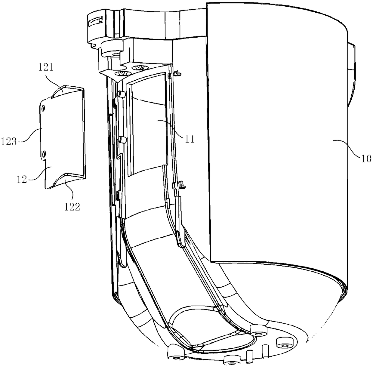
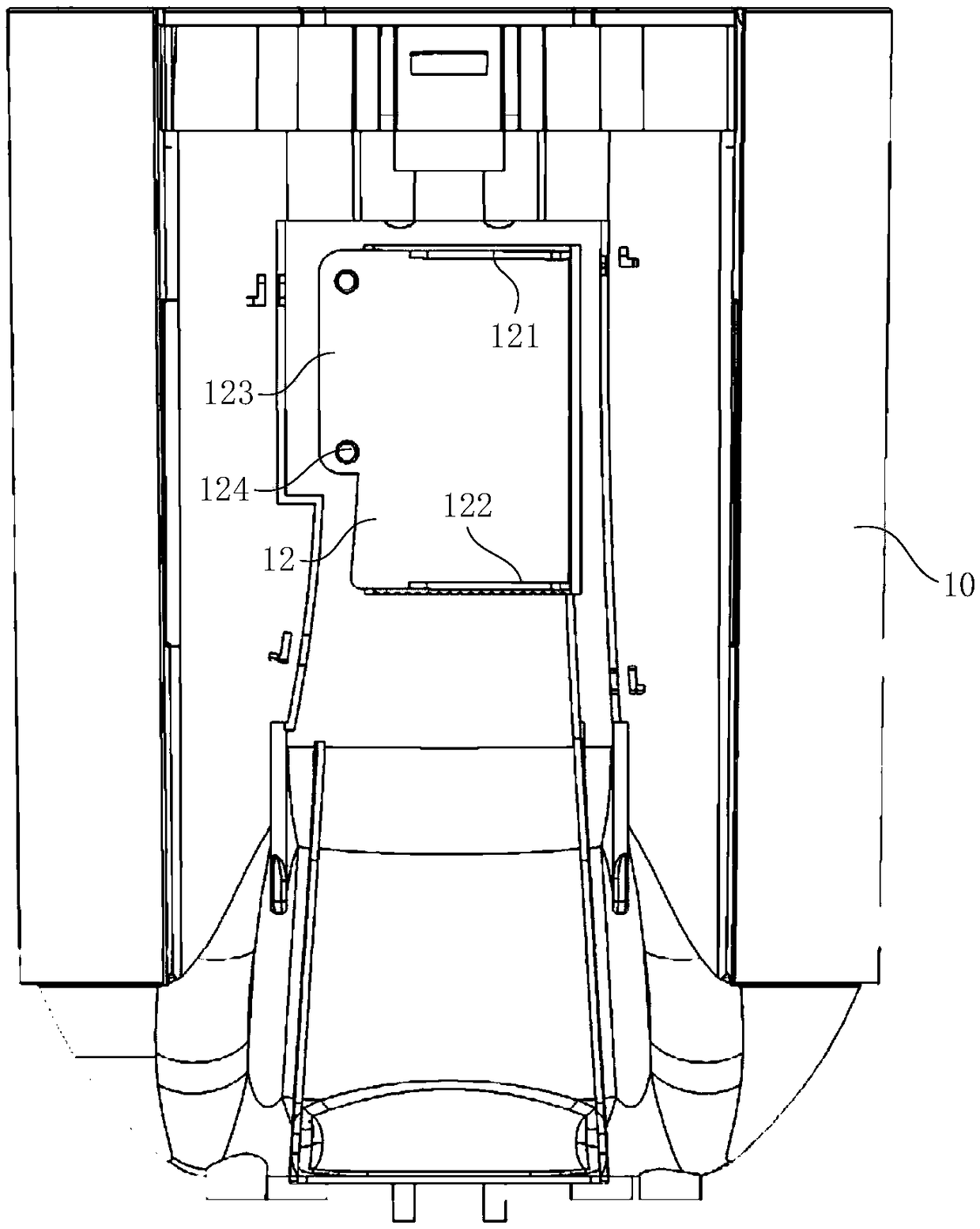
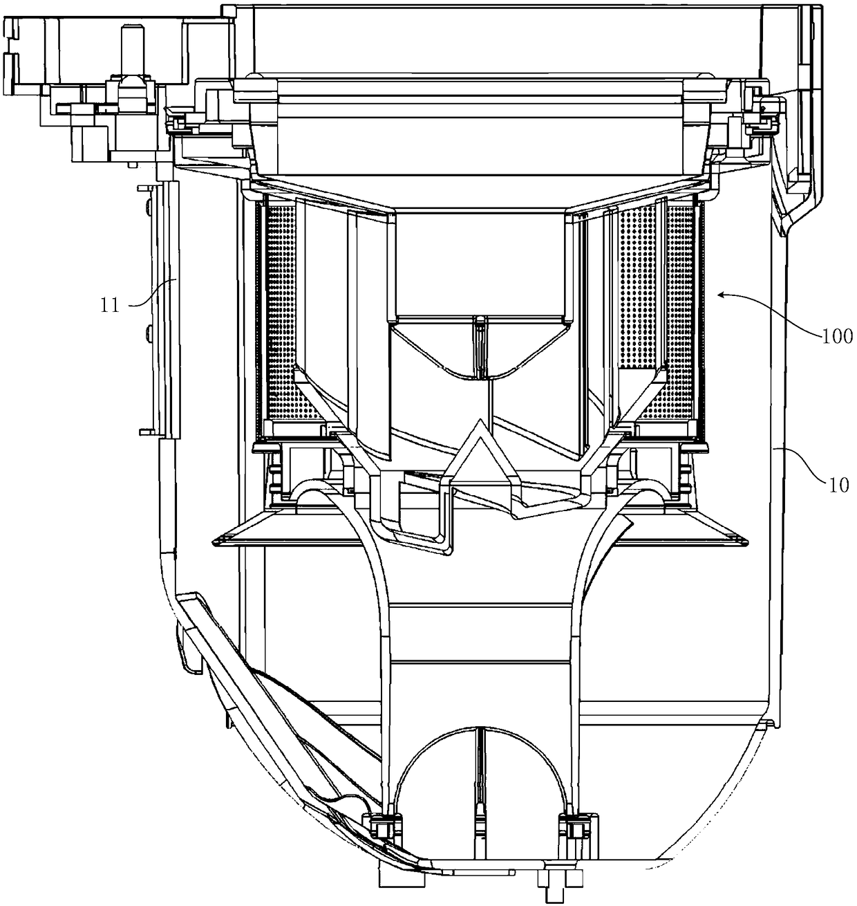
The invention discloses a cyclone separator. The cyclone separator comprises a first separation cavity, a second separation cavity, an air outlet and a dust discharge opening. The first separation cavity comprises a bottom surface in the reversely-conical structure and multiple air-guide blades in arc structures. The multiple air-guide blades are uniformly and spirally arranged onto the bottom surface in order to form multiple air channels. An air channel inlet is formed by an outer end of one air-guide blade and an outer end of an adjacent air-guide blade. An air channel outlet is formed by an inner end of one air-guide blade and an inner end of an adjacent air-guide blade. The first separation chamber communicates with the bottom end of the first separation cavity. The bottom surface ofthe second separation cavity is a spirally-downward channel which is coaxial to the bottom surface of the first separation cavity. The air outlet is arranged at the top end of the first separation cavity. The dust discharge opening is arranged at the tail end of a channel of the second separation cavity. The invention also discloses a filtering assembly. The cyclone separator is equipped with twoseparation cavities which can perform cyclone separation twice on dust-laden gas. Therefore, better filtering effect is obtained.

Description

technical field [0001] The invention relates to the field of vacuum cleaners, in particular to a cyclone separator and a filter assembly. Background technique [0002] In order to achieve a good filtering effect, the filter assembly of the existing vacuum cleaner usually has a multi-stage filtering function, wherein one-stage or two-stage filtration adopts a cyclone separation unit. The separation chamber of the existing cyclone separation unit is usually a single cylindrical or conical shape, and the filtering effect is not ideal. In addition, in order for the dust-laden gas to generate spiral motion in the cyclone separation unit, its air inlet is usually arranged tangentially. In this way, the dust-laden gas enters the interior of the cyclone separation unit along the tangential direction, and spirals along the inner wall to separate the dust. However, in the above-mentioned cyclone separation unit, the dust-laden gas must gradually generate a spiral motion under the gu...

Claims


Application Information

Patent Timeline
Patent Type & Authority Applications(China)
IPC IPC(8): A47L9/16A47L9/12A47L9/10
CPCA47L9/10A47L9/127A47L9/1608A47L9/1625
Inventor 檀冲孙书进徐龙
Owner PUPPY ELECTRONICS APPLIANCES INTERNET TECH (BEIJING) CO LTD
Why Eureka
Try Eureka