Full-speed oil purifying device

An oil purification and rapid technology, applied in chemical instruments and methods, liquid separation, separation methods, etc., can solve the complex structure of oil purification devices, complex distribution of pipelines, poor guarantee of structural stability and pipeline air tightness, etc. problems, to reduce the risk of oil spills, reduce the quantity, and increase the effect of airtightness

Pending Publication Date: 2018-11-06
镇江市长江机电设备厂有限公司
View PDF0 Cites 2 Cited by
  • Summary
  • Abstract
  • Description
  • Claims
  • Application Information

AI Technical Summary

Problems solved by technology

Due to the density difference of the mixed liquid, the heavier solid phase will start to stay down when the gravity exceeds the centrifuge, and will be thrown to the inner wall of the drum wall and flow to the slag discharge port, while the lighter liquid phase will Or the oil item will continue to 'climb' along the disc until it is discharged from the liquid discharge port on the upper end of the machine, but the existing oil purification device is often complex in structure, especially the distribution relationship between the various pipelines is relatively complicated, and its structural stability The airtightness of the pipeline is not guaranteed

Method used


Image

  • Full-speed oil purifying device
  • Full-speed oil purifying device

Examples


Embodiment Construction

[0022] In order to deepen the understanding of the present invention, the present invention will be further described below in conjunction with the embodiments and accompanying drawings. The embodiments are only used to explain the present invention and do not constitute a limitation to the protection scope of the present invention.

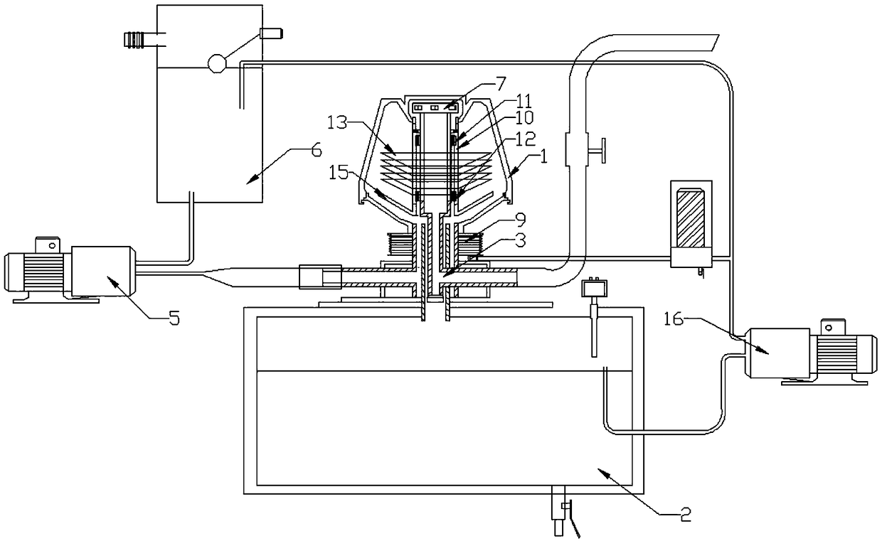
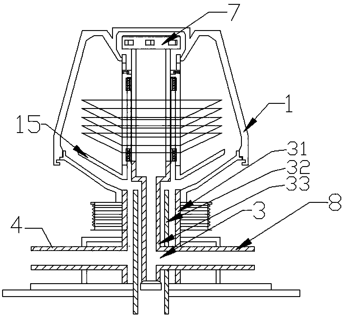
[0023] Such as figure 1 with figure 2 As shown, a fast oil purification device includes a drum 1 with a drum inner cavity and a dirt-holding box 2 arranged under the drum 1, and an oil pipe is arranged between the drum 1 and the dirt-holding box 2 System 3, such as figure 2 As shown, the oil pipe system 3 includes an oil inlet vertical pipe 31 , a slag outlet pipe 32 and a clean oil vertical outlet pipe 33 which are sleeved sequentially from outside to inside;

[0024] The upper end of the vertical oil inlet pipe 31 communicates with the inner cavity of the drum, and the lower end is connected with the upper wall of the dirt holding tank 2. T...


PUM


Abstract

The invention discloses a full-speed oil purifying device. The full-speed oil purifying device comprises a rotary drum having an inner chamber of the rotary drum and a dirt containing tank arranged below the rotary drum, an oil pipe system is arranged between the rotary drum and the dirt containing tank, the oil pipe system comprises an oil-inlet vertical pipe, a slag outlet pipe and a cleansing oil vertical outlet pipe which sleeve in order from outer to inner, a rotation shaft sleeved at an outer wall of the cleansing oil vertical outlet pipe is arranged in the inner chamber of the rotary drum, an upper end of the rotation shaft is connected with an inner wall of the rotary drum, the rotation shaft and the cleansing oil vertical outlet pipe are connected through an upper rotation bearingand a lower rotation bearing, several dirt containing dishes sleeve the rotation shaft. The full-speed oil purifying device has the advantages of compact structure, high purifying efficiency, and fast speed.

Description

technical field [0001] The invention relates to a flying oil purification device. Background technique [0002] When the drum runs at high speed, the mixed liquid material to be separated enters the bottom of the drum of the oil purification device from the feed pipe. When the mixed liquid flows out of the feed pipe, due to the centrifugal force, the components of the mixed liquid will flow countercurrently upwards. Due to the density difference of the mixed liquid, the heavier solid phase will start to stay down when the gravity exceeds the centrifuge, and will be thrown to the inner wall of the drum wall and flow to the slag discharge port, while the lighter liquid phase will Or the oil item will continue to 'climb' along the disc until it is discharged from the liquid discharge port on the upper end of the machine, but the existing oil purification device is often complex in structure, especially the distribution relationship between the various pipelines is relatively c...

Claims


Application Information

Patent Timeline
Patent Type & Authority Applications(China)
IPC IPC(8): B01D17/038
CPCB01D17/0217
Inventor 丁恒井张晓进
Owner 镇江市长江机电设备厂有限公司
Why Eureka
Try Eureka