
Centrifugal solid-liquid separator

A solid-liquid separator, centrifugal technology, applied in centrifuges, centrifuges with rotating drums, etc., can solve the problems of low separation efficiency, solid residues cannot be sent out in time, and the separator cannot operate continuously, etc. Wide range of applications and strong practicability

Pending Publication Date: 2018-11-06
DINGZHOU SIFENG ENVIRONMENTAL PROTECTION TECH
View PDF0 Cites 0 Cited by
  • Summary
  • Abstract
  • Description
  • Claims
  • Application Information

AI Technical Summary

Problems solved by technology

[0005] The purpose of the present invention is to provide a centrifugal solid-liquid separator. In order to solve the problem that the separated solid residue (or solid material) cannot be sent out in time when the centrifugal solid-liquid separator is working, it often needs to be shut down to take it out from the equipment. , so that the separator cannot work continuously, resulting in the technical problem of low separation efficiency

Method used


Image

  • Centrifugal solid-liquid separator
  • Centrifugal solid-liquid separator
  • Centrifugal solid-liquid separator

Examples


Embodiment 1

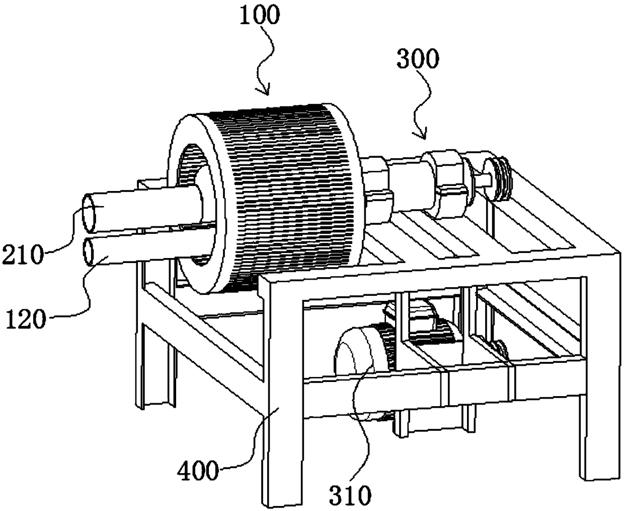
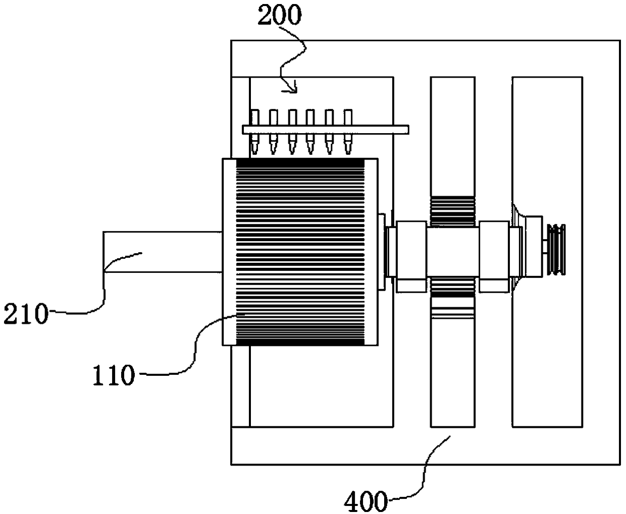
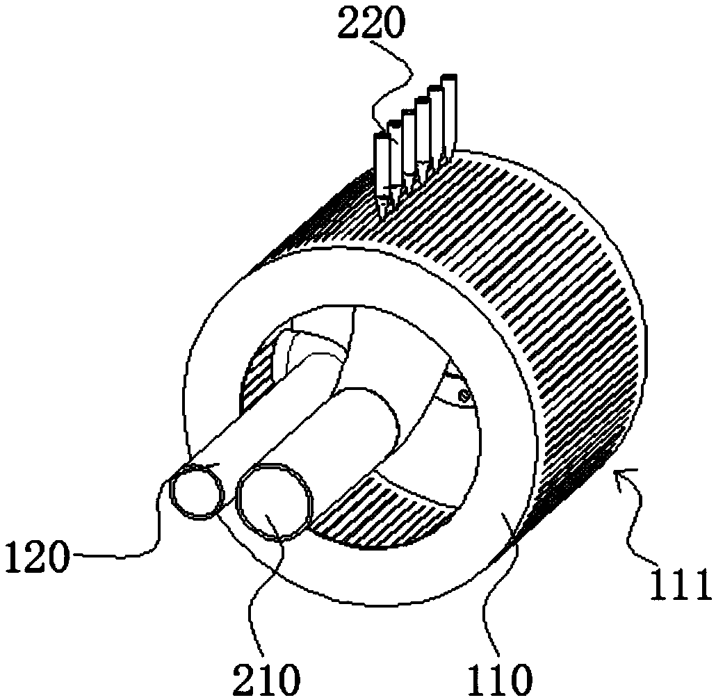
[0045] Such as Figure 1 to Figure 5 As shown, the first embodiment provides a centrifugal solid-liquid separator, including: a centrifuge body 100, a feed port for feeding solid-liquid mixture materials and a discharge device 200 for discharging solid materials; The machine body 100 includes a filter cylinder 110, the filter cylinder 110 is connected with a power assembly 300 for driving its rotation, and the filter cylinder 110 is provided with a water filtering structure 111 for filtering out the liquid material in the filter cylinder 110; The discharge device 200 includes a pneumatic assembly and a discharge pipe 210, and the air pressure assembly can provide high-speed air flow to blow the solid material in the filter cylinder 110 to the discharge pipe 210, and output through the discharge pipe 210; It communicates with the filter cylinder 110.

[0046] In the centrifugal solid-liquid separator, the solid-liquid mixture enters the filter screen cylinder 110 through the f...

Embodiment 2

[0067] Such as Figure 6 to Figure 9 As shown, the second embodiment also provides a centrifugal solid-liquid separator, the centrifugal solid-liquid separator includes parts and components with the same names and working principles as those in the first embodiment, and its structure is the same as that of the above-mentioned embodiment A centrifugal solid-liquid separator is basically the same, the differences are as follows.

[0068] In the second embodiment, the centrifuge body 100 also includes an outer cylinder 130, the outer cylinder 130 is arranged on the outside of the screen cylinder 110, and a water-holding annular cavity for accommodating liquid materials can be formed between the two; the water filtering structure 111 It communicates with the water-holding ring cavity, and the outer cylinder 130 is provided with a liquid outlet, and the liquid outlet communicates with the water-holding ring cavity.

[0069] Since the outer cylinder 130 is provided on the outside o...


PUM


Abstract

The invention relates to the technical field of solid-liquid separation equipment and provides a centrifugal solid-liquid separator in order to solve the technical problems that when a centrifugal solid-liquid separator operates, separated solid-state residues cannot be sent out in time so that the separator cannot conduct continuous operation and the separation efficiency is low. The centrifugalsolid-liquid separator related by the invention comprises a centrifugal machine body, a feed port and a discharge device. The centrifugal machine body comprises a filter screen drum. The filter screendrum is connected with a power assembly. The filter screen drum is provided with a draining structure. The discharge device comprises an air compression assembly and a discharge pipe. The feed port communicates with the filter screen drum. The centrifugal solid-liquid separator conducts discharging without a machine halt, can realize continuous operation and is high in separation efficiency.

Description

technical field [0001] The invention relates to the technical field of solid-liquid separation equipment, in particular to a centrifugal solid-liquid separator. Background technique [0002] With the development of social economy and the improvement of people's living standards, the proportion of animal food in people's diet structure is getting higher and higher, and the scale of livestock and poultry breeding has also experienced unprecedented development. While the breeding industry is developing, it also brings about the problem of livestock and poultry manure disposal. Due to the high moisture content and foul smell of livestock and poultry manure, it is inconvenient to transport and apply, which also increases the difficulty of reusing livestock and poultry manure, and at the same time brings environmental pollution problems. Moreover, livestock and poultry manure contains a large amount of organic matter and nutrients, if it cannot be utilized and discharged directly...

Claims


Application Information

Patent Timeline
Patent Type & Authority Applications(China)
IPC IPC(8): B04B1/00B04B11/02B04B7/16B04B9/02
CPCB04B1/00B04B7/16B04B9/02B04B11/02
Inventor 赵峰
Owner DINGZHOU SIFENG ENVIRONMENTAL PROTECTION TECH
Learn More