
Steel wire rope oiling gun

A steel wire rope and oiling technology, applied in spraying devices, liquid spraying devices, etc., can solve the problems of oil dripping, oil dripping, reduce friction coefficient, etc., achieve uniform spraying degree, improve oiling efficiency, and ensure oiling effect Effect

Active Publication Date: 2018-11-06
LUOYANG INST OF SCI & TECH
View PDF6 Cites 0 Cited by
  • Summary
  • Abstract
  • Description
  • Claims
  • Application Information

AI Technical Summary

Problems solved by technology

However, the steel wire rope is scrapped in order to prevent corrosion. The thickness of the oil film on the surface of the steel wire rope has certain requirements. Clean up, if it is serious, it will affect the use of the wire rope
Through the oiling method of the oil tank, a large amount of oil is stained on the surface of the steel wire rope, and even the rope core of the steel wire rope is full of oil, resulting in a large waste of grease and serious oil dripping
Too much oil in some workplaces will reduce the friction coefficient and cause adverse effects on equipment

Method used


Image

  • Steel wire rope oiling gun
  • Steel wire rope oiling gun
  • Steel wire rope oiling gun

Examples


Embodiment Construction

[0050] In order to further illustrate the technical means and functions adopted by the present invention to achieve the intended invention purpose, the following will be described in detail in conjunction with the accompanying drawings and preferred embodiments.

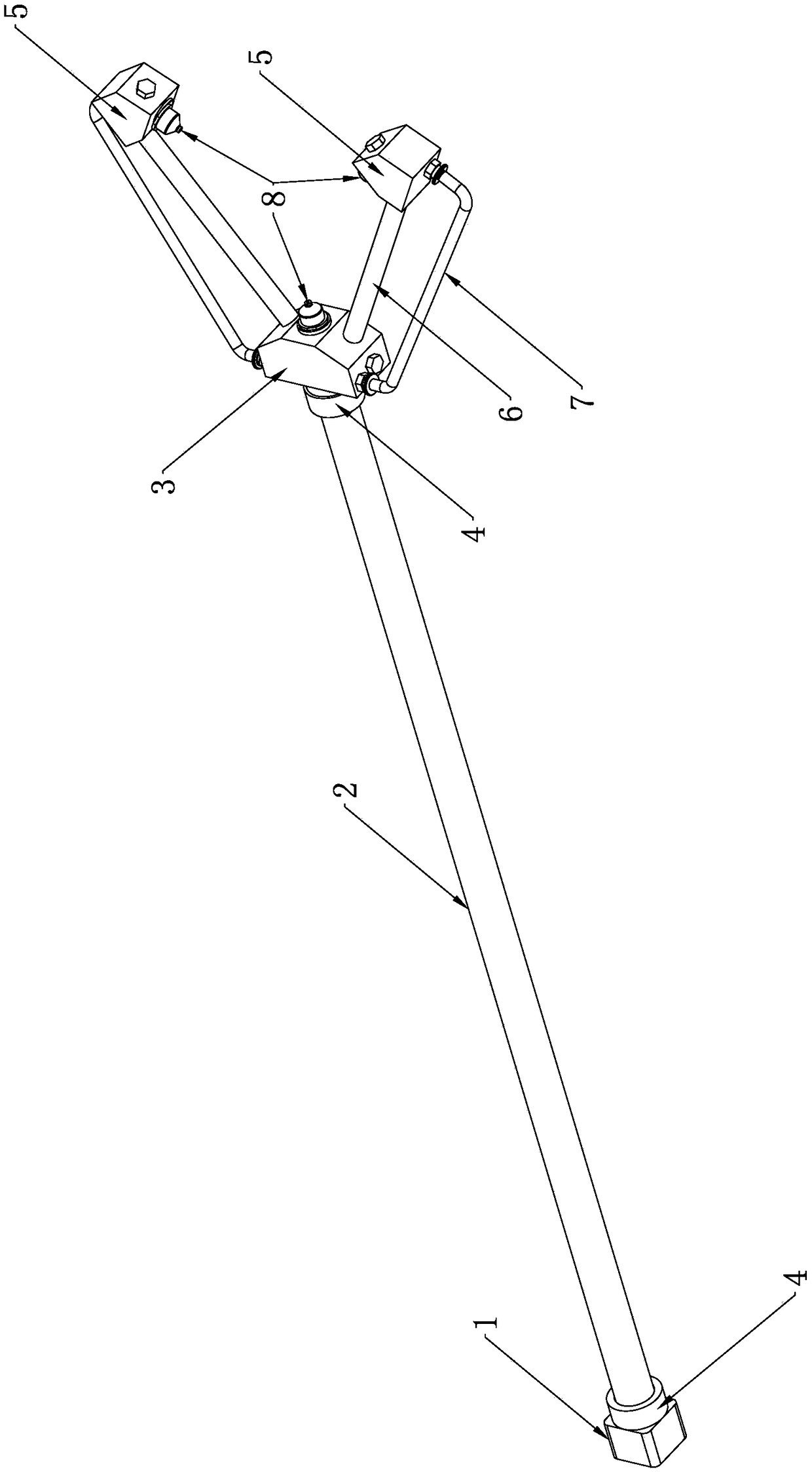
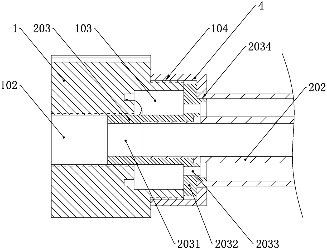
[0051] see figure 1, a wire rope oiling gun, comprising an oil inlet head 1, a gun shaft 2, a distribution head 3, a mixing nozzle 5, the oil inlet head 1 is respectively connected with an oil inlet pipe and an air inlet pipe to realize the supply of oil and gas. One end of the gun shaft 2 is connected with the oil inlet head 1 and compressed by a sealing pressure ring 4 , and the other end is connected with the distribution head 3 and is compressed by another sealing pressure ring 4 . The distribution head 3 is connected to the mixing nozzle 5 through a group of oil pipes 6 and air pipes 7 respectively, and a nozzle 8 is respectively installed on the distribution head 3 and the two mixing nozzles 5 . Through the gu...


PUM


Abstract

The invention discloses a steel wire rope oiling gun. The steel wire rope oiling gun comprises an oil inlet head, a gun rod, a distribution head and two mixing spray heads, the oil inlet head correspondingly communicates with an oil inlet pipe and a gas inlet pipe, one end of the gun rod is connected with the oil inlet head and is tightly pressed through a sealing pressing ring, the other end of the gun rod is connected with the distribution head and is tightly pressed through the other sealing pressing ring, the distribution head is connected with the two mixing spray heads through a group ofoil pipes and a groups of gas pipes correspondingly, and the distribution head and the two mixing spray heads each are provided with a nozzle. Oil and gas supplied from the oil inlet head are separately conveyed into the distribution head through the gun rod, the oil and the gas are distributed into three groups through the distribution head, one group of oil and gas is directly sprayed out through the nozzle arranged on the distribution head, and the other two groups of ol and gas enter the two mixing spray heads through the group of oil pipes and the group of gas pipes correspondingly, andthen are sprayed out through the nozzles arranged on the mixing spray heads correspondingly. According to the steel wire rope oiling gun, the three nozzles are arranged in a triangular shape so that the atomizing area of the three nozzles can completely cover the outer circle surface of a steel wire rope, then the efficiency of the nozzles is improved, and the spraying effect is guaranteed at thesame time.

Description

technical field [0001] The invention belongs to the technical field of steel wire rope oiling, in particular to a steel wire rope oiling gun. Background technique [0002] After a long time of use, the surface of the wire rope will be covered with dust and other debris, which will greatly affect its performance. If it continues to be used, it will reduce the service life of the wire rope and wear the working wheel. In severe cases, it will even cause the wire rope to break. , which poses a serious threat to equipment and personal safety, so oiling the wire rope is an essential work. [0003] Most of the existing steel wire rope oiling devices use an oil tank to oil the steel wire rope, that is, there are through holes for the steel wire rope to pass through the front and rear of the oil tank shell, and the steel wire rope moves along a straight line under the guidance of the rope stabilization wheel. Oiling is achieved by immersing the wire rope in the oil tank while the wi...

Claims


Application Information

Patent Timeline
Patent Type & Authority Applications(China)
IPC IPC(8): B05B7/02B05B7/04B05B13/02
CPCB05B7/02B05B7/04B05B13/0278
Inventor 李平李彦彬雷金龙付生辉万红光
Owner LUOYANG INST OF SCI & TECH
Learn More