Automatic waste collection device of stamping die

A technology for automatically collecting and stamping dies, applied in the field of stamping dies, can solve the problems of carrying damaged products, time-consuming and laborious cleaning of scraps, cracking knife edges, etc., to achieve the effect of improving work efficiency

Inactive Publication Date: 2018-11-06
FOSHAN KUIFENG BUSINESS CONSULTATION SERVICES CO LTD
View PDF0 Cites 13 Cited by
  • Summary
  • Abstract
  • Description
  • Claims
  • Application Information

AI Technical Summary

Problems solved by technology

[0003] As we all know, waste materials in stamping production account for 30% to 70% of stamping materials. Poor removal of stamping waste materials is a common problem in various faults of molds. Accumulated waste carries bad products and cracks the edge of the knife

Method used


Image

  • Automatic waste collection device of stamping die
  • Automatic waste collection device of stamping die
  • Automatic waste collection device of stamping die

Examples


Embodiment 1

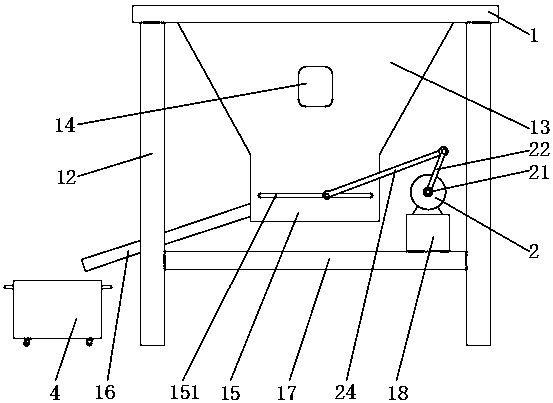
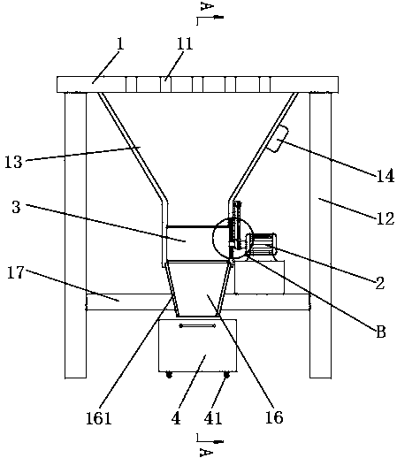
[0028] Example 1, see Figure 1-4 , the present invention provides a technical solution: a stamping die automatic waste collection device, including a stamping platform 1, a motor 2, a push plate 3 and a waste box 4, the top of the stamping platform 1 is 1.2 meters away from the ground, and the top of the stamping platform 1 is installed There is a stamping mold, and a mold punching hole 11 is provided inside the stamping platform 1. The mold punching hole 11 corresponds to the position where the lower mold of the mold installed on the top of the stamping platform 1 is impacted and pierced by the upper mold of the mold fixed on the top of the press. To accept the metal block punched out after piercing, the four ends of the bottom of the stamping platform 1 are fixed with support legs 12 by welding, and the inner sides of the four support legs 12 are horizontally fixed with a horizontal plate 17, which can support the four support legs 12 , other tools needed for stamping can a...

Embodiment 2

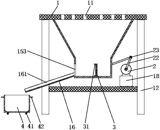
[0039] Example 2, see Figure 5 , in Embodiment 1, the top and bottom of both sides of the pusher plate 3 are provided with a block 31 inclined inwardly, and the two sides perpendicular to the material receiving box 15 and the slide hole 151 are provided with a discharge port 153, The motor 2 drives the second connecting rod 24 to push the push plate 3 to reciprocate left and right, and the waste materials can be pushed out from the discharge ports 153 on both sides of the material receiving box 15 respectively, and then enter the conveying plates 16 on both sides and be transported to both sides waste bin 4.

Embodiment 3

[0040] Embodiment 3. In Embodiment 1, a fixed head 21 is fixed at the output end of the motor 2, a transmission shaft is fixed on the other side of the fixed head 21, and first connecting rods 22 are respectively fixed on both sides of the transmission shaft. The connecting rod 22 will rotate along with the output end of the motor 2, and the end of the first connecting rod 22 is rotated to connect the second connecting rod 24 through the rotating shaft 23 respectively, and the two sides of the chute 152 are opened in the receiving box 15 respectively. Sliding hole 151 is opened, and cylinder 32 is respectively fixed in the middle of both sides of pushing plate 3 close to sliding hole 151, and both sides of cylinder 32 pass through sliding hole 151 and second connecting rod 24 are rotated and connected respectively. By turning on the motor 2, the motor 2 will drive the two first connecting rods 22 to rotate together, and the first connecting rod 22 will drive the second connecti...


PUM


Abstract

The invention discloses an automatic waste collection device of a stamping die. The automatic waste collection device of the stamping die comprises a stamping platform, a motor, a pushing plate and awaste box. The motor is fixed to the top of a motor base. A fixing head is fixed to the output end of the motor. A first connecting rod is fixed to the outer side of the fixing head. The end of the first connecting rod is rotatably connected with a second connecting rod. A guide box is arranged at the bottom of the stamping platform. A collection box is connected to the bottom of the guide box. Asliding hole is formed in the middle of one side of the collection box. Sliding grooves are formed in the inner walls of the two sides of the collection box. The collection box is connected with the pushing plate through the sliding grooves. A cylinder is fixed to the middle of one side of the pushing plate. One side of the cylinder penetrates through the sliding hole to be rotatably connected with the second connecting rod. A discharging port is formed in the other side, perpendicular to the sliding hole, of the collection box. A conveying plate is fixed to the bottom of the discharging port.The waste box is placed under the bottom of the conveying end of the conveying plate. According to the automatic waste collection device, the pushing plate connected to the end of the second connecting rod is driven by the motor to reciprocate leftwards and rightwards in the collection box so as to automatically push waste into the waste box.

Description

technical field [0001] The invention relates to the technical field of stamping dies, in particular to a stamping die automatic waste collection device. Background technique [0002] Stamping is a pressure processing method that uses a mold installed on a press to apply pressure to the material at room temperature to cause separation or plastic deformation to obtain the required parts. [0003] As we all know, waste materials in stamping production account for 30% to 70% of stamping materials. Poor removal of stamping waste materials is a common problem in various faults of molds. The accumulated waste will damage the product and crack the edge of the knife. Therefore, whether the removal of waste is smooth is of great significance for improving production efficiency, reducing labor intensity, and ensuring product quality and mold status. Contents of the invention [0004] The object of the present invention is to provide an automatic waste collection device for stamping...

Claims


Application Information

Patent Timeline
Patent Type & Authority Applications(China)
IPC IPC(8): B21D45/00B21D43/20
CPCB21D45/00B21D43/20
Inventor 梁登
Owner FOSHAN KUIFENG BUSINESS CONSULTATION SERVICES CO LTD
Why Eureka
Try Eureka