
Clamping device for computer shell machining

A technology for clamping devices and shells, applied in positioning devices, metal processing equipment, metal processing machinery parts, etc., can solve the problems of high cost, complex structure, poor pressing quality, etc., and achieve high clamping efficiency and low cost Inexpensive, good clamping quality results

Pending Publication Date: 2018-11-06
江苏匠准精密组件有限公司
View PDF0 Cites 5 Cited by
  • Summary
  • Abstract
  • Description
  • Claims
  • Application Information

AI Technical Summary

Problems solved by technology

[0002] The notebook computer casing includes the upper casing and the lower casing, that is, the bottom of the notebook computer. During the production of the lower casing, the surrounding end faces and surrounding features need to be processed by NC after casting, and the size requirements for product processing are strict; Around, the edge of the product needs to be pressed, and the structure of the product itself is not conducive to increasing the way of pressing the cylinder. The previous scheme used the electromagnet to absorb the pressure plate, but the structure is complicated, the cost is too high, and the quality of the pressing is not good

Method used


Image

  • Clamping device for computer shell machining
  • Clamping device for computer shell machining
  • Clamping device for computer shell machining

Examples


Embodiment 1

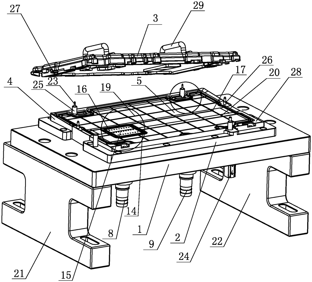
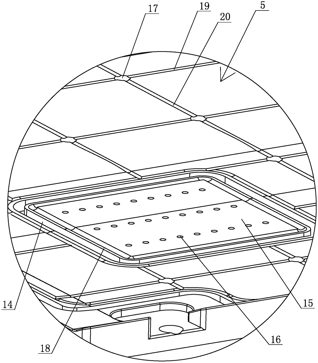
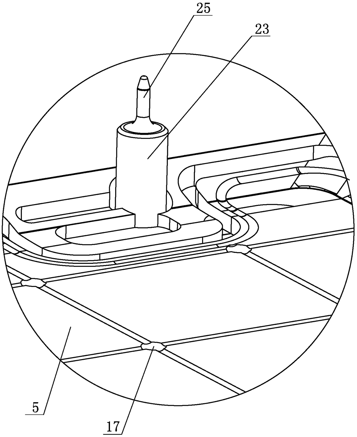
[0021] Embodiment one: see Figure 1~4 As shown, a clamping device for computer case processing includes a bracket, a fixed plate 1, a product carrying plate 2 and a pressing plate 3, the bottom of the fixed plate 1 is installed on the support, and the product carrying plate 2 The bottom is installed on the top surface of the fixed plate 1, and the pressing plate 3 is placed on the product carrying plate 2; a raised block 4 is arranged on the top surface of the product carrying plate 2, and the raised block 4 A product placement groove 5 is provided on the top surface of the top surface, and the bottom surface of the pressing plate 3 is placed on the top outer edge surface of the raised block 4; the fixed plate 1 is provided with a left through hole 6 and a right through hole. hole 7, a first vacuum joint 8 is installed in the left side through hole 6, a second vacuum joint 9 is installed in the right side through hole 7, and the first vacuum joint 8 and the second vacuum join...


PUM


Abstract

The invention discloses a clamping device for computer shell machining. The clamping device is characterized by comprising a support, a fixed plate, a product bearing plate and a pressing plate; a raised block is arranged on the top surface of the product bearing plate, a product placing groove is formed in the top face of the raised block, and the periphery of the bottom surface of the pressing plate is arranged on the top outer edge surface of the raised block; a left side through hole and a right side through hole are formed in the fixed plat, a first vacuum connector is installed in the left through hole, and a second vacuum connector is installed in the right through hole; a sealed first groove and a sealed second groove are formed in the bottom of the product bearing plate, the leftthrough hole communicates with the first groove, and the right through hole communicates with the second groove; a plurality of breathable holes and ventilation holes are formed in the product placinggroove, suction holes communicate with the first groove, and the ventilation holes communicate with the second groove. The clamping device for computer shell machining improves the clamping efficiency and the clamping quality of products.

Description

technical field [0001] The invention relates to a clamping device, in particular to a clamping device for computer case processing. Background technique [0002] The notebook computer casing includes the upper casing and the lower casing, that is, the bottom of the notebook computer. During the production of the lower casing, the surrounding end faces and surrounding features need to be processed by NC after casting, and the size requirements for product processing are strict; Around, the edge of the product needs to be pressed, and the structure of the product itself is not conducive to increasing the way of pressing the cylinder. The previous plan used the electromagnet to absorb the pressure plate, but the structure is complicated, the cost is too high, and the quality of the pressing is not good. Therefore, how to solve the above technical problems is the direction that those skilled in the art need to work on. Contents of the invention [0003] The object of the pres...

Claims


Application Information

Patent Timeline
Patent Type & Authority Applications(China)
IPC IPC(8): B23Q3/08
CPCB23Q3/088
Inventor 李宁姜振涛
Owner 江苏匠准精密组件有限公司
Learn More