Conveying equipment

A technology for conveying equipment and conveyor belts, which is applied in the field of transmission and can solve problems such as insufficient conveyance

Pending Publication Date: 2018-11-06
KUNSHAN DONGWEI MACHINERY CO LTD
View PDF0 Cites 4 Cited by
  • Summary
  • Abstract
  • Description
  • Claims
  • Application Information

AI Technical Summary

Problems solved by technology

[0005] Therefore, the technical problem to be solved by the present invention lies in the conveying

Method used


Image

  • Conveying equipment
  • Conveying equipment
  • Conveying equipment

Examples


Embodiment 1

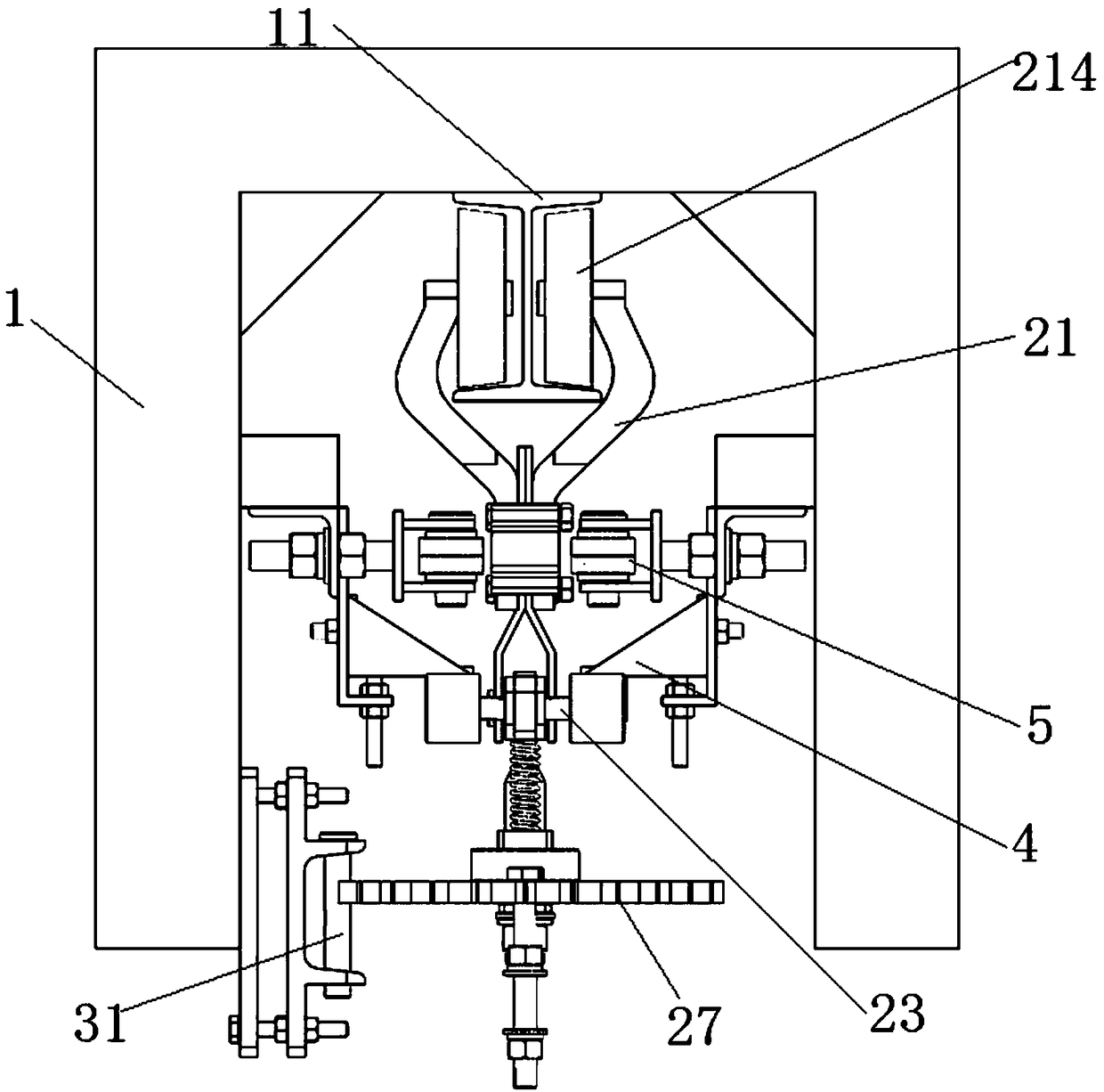
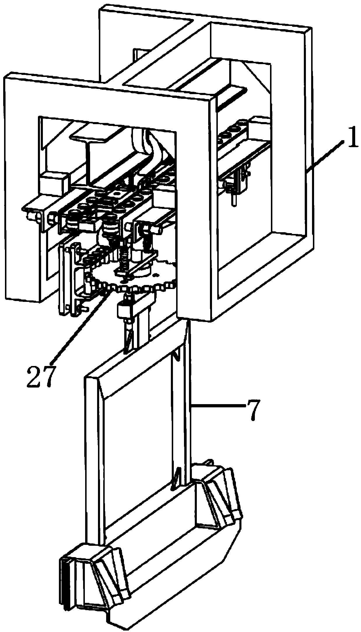
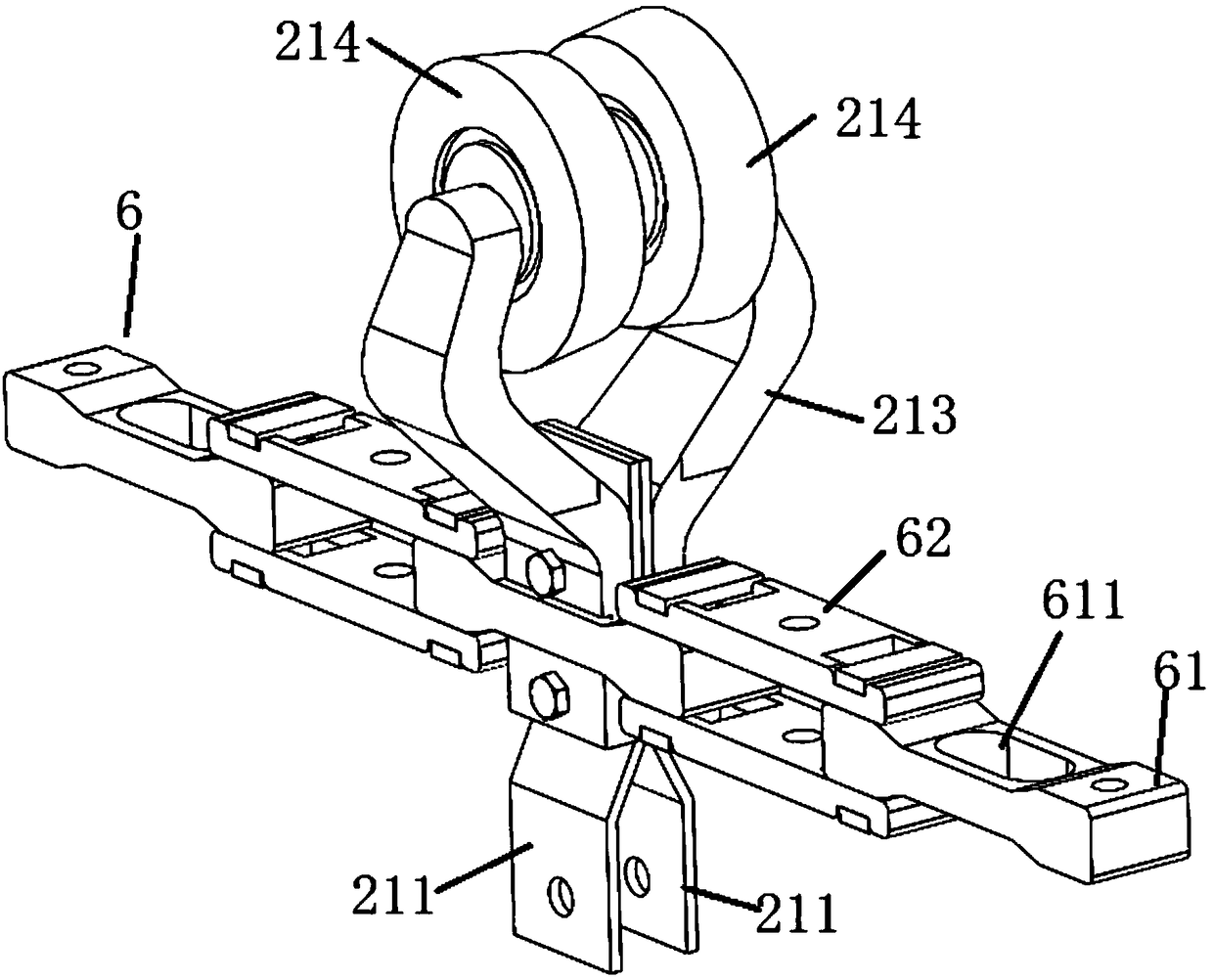
[0079] This embodiment provides a conveying device, which includes a base frame 1 , a transmission chain 6 and a plurality of suspension structures 2 . Wherein, the transmission chain 6 is a closed loop and is slidably arranged on the base frame 1 . For example, the transmission chain 6 is a chain, and the two ends of the pedestal 1 are respectively provided with a driving wheel and a driven wheel. The transmission chain 6 is wound around the outside of the driving wheel and the driven wheel. The driving wheel is driven to rotate, and the driven wheel is driven to rotate through the transmission chain 6 to realize the slidable arrangement of the transmission chain 6 on the base frame 1 .

[0080] A plurality of suspension structures 2 are vertically suspended on the transmission chain 6 , a required gap is reserved between two adjacent suspension structures 2 , and the transmission chain 6 drives the suspension structures 2 to slide linearly on the base frame 1 . like figure...

Embodiment 2

[0119] This embodiment provides a conveying device, which is different from the conveying device provided in Embodiment 1 in that:

[0120] The rack 31 is not provided on the base frame 1, and the rotating member 27 may or may not be a gear. For example, a turntable is used instead of a gear, or a rotating member 27 of any shape. For example, the rotating part 27 is a square, T-shaped, S-shaped rotating wheel or a rotating disk, and only the hanger 7 needs to be installed on the rotating part 27 to get final product. The hanger 7 can be directly fixed on the rotating member 27 , or can be suspended or detachably installed on the rotating member 27 . When the rack 31 is not provided on the base frame 1, a separate driver, such as a rotating motor, is required to drive the rotating member 27 to rotate. Other structures of the conveying equipment in this embodiment are the same as those in Embodiment 1, and will not be repeated here.

Embodiment 3

[0122] This embodiment provides a conveying device, which is different from the conveying device provided in Embodiment 1 or Embodiment 2 in that:

[0123] The abutment surface 43 may not be a horizontal plane, the first slope surface 41 and the second slope surface 42 may be asymmetrical, and the abutment surface 43 may be an uneven surface. Since the abutment surface 43 is located below the first slope surface 41, as long as the When the roller 235 in the positioning mechanism abuts against the abutting surface 43, the bottom of the limiting member 22 can be kept completely away from the rotating member 27, and the limiting effect on the rotating member 27 can be released. Whether the abutting surface 43 is a horizontal plane is not limited.

[0124] As a second alternative implementation of Example 2, in the horizontal direction, the sum of the length of the abutting surface 43 and the length of the second slope 42 is greater than the arc length of the angle required for th...


PUM


Abstract

The invention discloses conveying equipment which comprises a base frame, a conveyor belt slidably arranged on the base frame and a suspending structure suspended on the conveyor belt vertically, wherein the suspending structure comprises a fixed rack, a rotating part and a limiting mechanism; the top of the fixed rack is fixed to the conveyor belt; the rotating part is rotatably and horizontallymounted at the bottom of the fixed rack; the limiting mechanism is provided with a connecting part rotatably mounted on the fixed rack and limiting parts separately mounted at two ends of the connecting part, the connecting part is driven by driving force to rotate to drive the bottoms of the limiting parts to be inserted onto the rotating part or to be separated from the rotating part. The connecting part forms a lever on the fixed rack, and the connecting part rotates anticlockwise, so that the bottoms of the limiting parts are inserted onto the rotating part, and the rotating part and the fixed rack are in a relatively fixed state; when the connecting part rotates clockwise, the limiting parts relieve limit to the rotating part, so that the rotating part can rotate at a needed angle relative to the fixed rack, and therefore, the working accuracy of the conveying equipment is improved.

Description

technical field [0001] The invention relates to the field of transmission technology, in particular to a conveying device. Background technique [0002] With the continuous development of automation technology, in the surface treatment industry, logistics, machinery manufacturing and other industries, in the assembly line, the use of robots to replace manual loading and unloading or loading and unloading is becoming more and more widely used. Among them, it is a very conventional mode to use conveying equipment and robots to undertake the conveying of workpieces. [0003] Before the existing conveying equipment transports the workpiece to the loading station or the unloading station, it needs to turn the workpiece to a certain angle, such as 180 degrees, so that the robot can work on the workpiece. Therefore, a plurality of suspension structures are suspended on the suspension chain in the existing conveying equipment; any suspension structure includes a fixed frame vertica...

Claims


Application Information

Patent Timeline
IPC IPC(8): B24B41/00B23Q7/00
CPCB24B41/005B23Q7/007
Inventor 韩友生方荣平杨彦博
Owner KUNSHAN DONGWEI MACHINERY CO LTD
Why Eureka
Try Eureka