
Holding column type connecting device used between two carriers

A technology for connecting devices and carriers, applied in the direction of tugboats, etc., can solve the problems such as the inability to meet the geometric size and motion characteristics of the target simulation target, hidden dangers of navigation safety, etc., and achieve the effects of compact structure, self-locking function, and convenient operation.

Inactive Publication Date: 2018-11-06
CHINA SHIP SCIENTIFIC RESEARCH CENTER (THE 702 INSTITUTE OF CHINA SHIPBUILDING INDUSTRY CORPORATION)
View PDF7 Cites 1 Cited by
  • Summary
  • Abstract
  • Description
  • Claims
  • Application Information

AI Technical Summary

Problems solved by technology

[0002] The carrier connection is similar to the connection of numerous tugboats driven by civilian tugboats. The tugboat connection is generally connected by a certain length of steel cable or cable, but this method applied to new surface targets will not meet the geometric dimensions and motion characteristics of target simulation targets.
Because, in order to reduce the mutual influence between the tugboats, it is generally solved by lengthening the length of the steel cable or the length of the steel cable and increasing the distance between the hulls, but at this time the two ships are equivalent to sailing separately, which can only reflect their respective geometric dimensions and motion characteristics. It also poses a threat to navigation safety

Method used


Image

  • Holding column type connecting device used between two carriers
  • Holding column type connecting device used between two carriers
  • Holding column type connecting device used between two carriers

Examples


Embodiment Construction

[0017] The specific implementation manner of the present invention will be described below in conjunction with the accompanying drawings.

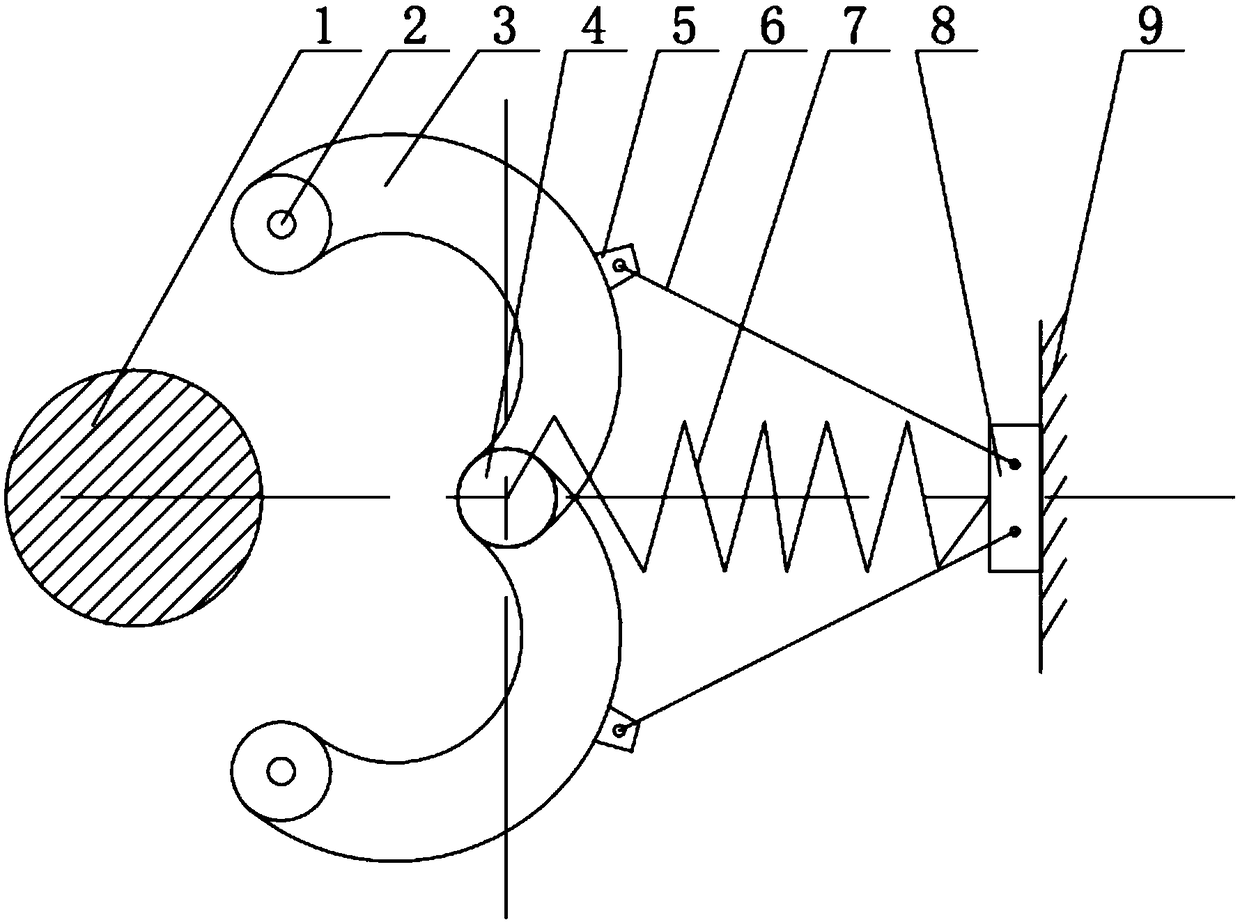
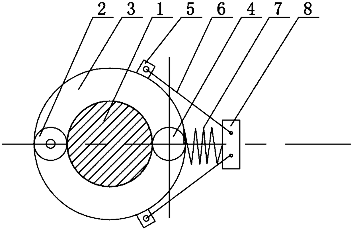
[0018] Such as figure 1 , figure 2 and image 3 As shown, the column-hugging connecting device used between the two carriers in this embodiment includes a fixed block 8, and one end of the fixed block 8 is connected to the movable shaft 4 through the long-stroke spring 7, and a pair of symmetrical petals are installed on the movable shaft 4. 3. The heads of the two petals 3 are provided with pin holes 2, and the two petals 3 are closed to surround the column 1; the outer sides of the two petals 3 are provided with a fixed bracket 5, the fixed bracket 5 and the fixed block 8 They are connected by telescopic connecting rods 6, and the two telescopic connecting rods 6 are symmetrically arranged on both sides of the long stroke spring 7.

[0019] A plurality of carriers are arranged at intervals, and both ends of each carrier are provided ...


PUM


Abstract

The invention relates to a holding column type connecting device used between two carriers. The holding column type connecting device used between the two carriers comprises a fixed block; one end ofthe fixed block is connected with a movable rotating shaft through a long-stroke spring; a pair of symmetric flap bodies is mounted on the movable rotating shaft; pin holes are formed in the head parts of both the two flap bodies; the two flap bodies surround an upright after being closed; fixing brackets are arranged on the external sides of the two flap bodies; the fixing brackets are connectedwith the fixed block through telescopic connecting rods; the two telescopic connecting rods are symmetrically placed on the two sides of the long-stroke spring. According to the holding column type connecting device used between the two carriers, the structure is compact and reasonable; the operation is convenient; through adoption of the holding column type connecting device, the opening and closing motions of the connection between the two carriers can be conveniently realized to satisfy a self-locking function; and meanwhile, automatic opening and closing in any horizontal direction can berealized; and additional load of a connecting body is supported.

Description

technical field [0001] The invention relates to the technical field of connection devices, in particular to a pillar-hugging connection device used between two carriers. Background technique [0002] The carrier connection is similar to the connection of numerous tugboats driven by civilian tugboats. The tugboat connection is generally connected by a certain length of steel cable or steel cable. However, this method applied to new surface targets will not meet the geometric dimensions and motion characteristics of target simulation targets. Because, in order to reduce the mutual influence between the tugboats, it is generally solved by lengthening the length of the steel cable or the length of the steel cable and increasing the distance between the hulls, but at this time the two ships are equivalent to sailing separately, which can only reflect their respective geometric dimensions and motion characteristics. It also brings hidden dangers to navigation safety. [0003] For...

Claims


Application Information

Patent Timeline
IPC IPC(8): B63B35/68
CPCB63B35/68
Inventor 王骏超倪其军周谦张辉郭昂陈嘉伟
Owner CHINA SHIP SCIENTIFIC RESEARCH CENTER (THE 702 INSTITUTE OF CHINA SHIPBUILDING INDUSTRY CORPORATION)
Learn More