
Waste compression equipment

A garbage compression and equipment technology, which is applied in the direction of garbage transmission, garbage collection, garbage cleaning, etc., can solve the problems of inability to dock and unload 3-ton garbage collection vehicles, high requirements for civil engineering, and large floor space, etc., and achieve weight reduction and civil engineering The effect of cost reduction and small footprint

Inactive Publication Date: 2018-11-06
山东海沃嘉美环境工程有限公司
View PDF7 Cites 0 Cited by
  • Summary
  • Abstract
  • Description
  • Claims
  • Application Information

AI Technical Summary

Problems solved by technology

[0003] The invention proposes a garbage compression equipment, which solves the problems in the prior art that the garbage compression equipment occupies a large area, has high requirements for civil engineering, and cannot be docked with a 3-ton garbage collection vehicle for unloading.

Method used


Image

  • Waste compression equipment
  • Waste compression equipment

Examples


Embodiment

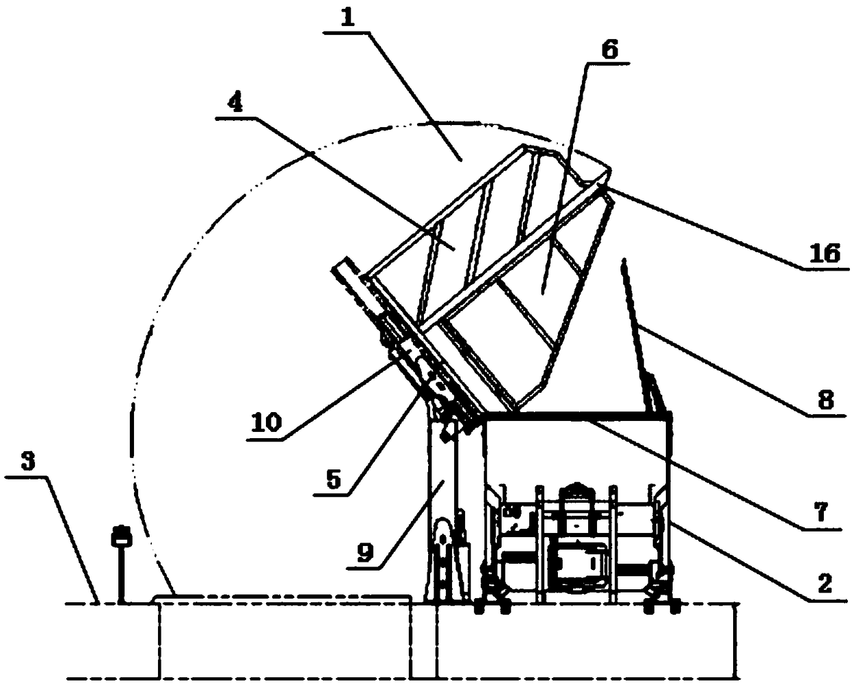
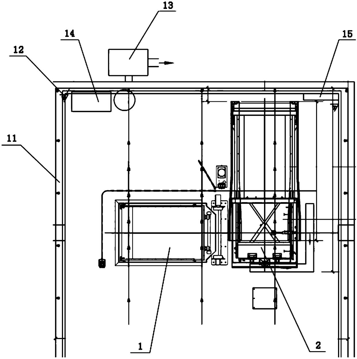
[0020] Such as figure 1 , 2 As shown, a garbage compression equipment includes a discharge hopper 1 and a compressor case 2, the discharge hopper 1 and the compressor case 2 are connected in a detachable manner, the discharge hopper 1 is located on one side of the compressor case 2, and the lower part of the discharge hopper 1 is placed Below the ground 3, the unloading hopper 1 is composed of a hopper cavity 4, a hopper back plate 5 and a hopper side plate 6, the hopper side plate 6 is rotatably mounted on the hopper back plate 5, and the hopper back plate 5 is connected with the material lifting and discharging mechanism The compressor box 2 is connected, and the position corresponding to the top of the compressor box 2 and the discharge hopper 1 is provided with a box opening 7, and a box cover 8 is provided on the box opening 7. When unloading, the discharge hopper 1 is discharged by lifting The mechanism moves to the top of the opening 7 of the box body to perform garbag...


PUM


Abstract

The invention provides waste compression equipment which comprises an unloading hopper and a compressor box body, wherein the unloading hopper and the compression box body are separately connected, the unloading hopper is located on one side of the compression box body, the lower part of the unloading hopper is placed under the ground and the unloading hopper is composed of a hopper accommodatingcavity, a hopper back plate and a hopper side plate; the hopper side plate is rotatably mounted on the hopper back plate, the hopper back plate is connected to the compressor box body through a lifting and unloading mechanism, a box body opening is formed in a position, corresponding to the unloading hopper, on the top of the compressor box body, and a box body cover plate is arranged at the box body opening. During unloading, the unloading hopper moves above the box body opening through the lifting and unloading mechanism to pour waste. The waste compression equipment in a separated design ofthe unloading hopper and the compressor box body solves the problem that original movable waste compression equipment cannot be connected to a 3-tonnage refuse collector, is small in occupied area ofequipment, solves the problem that it is hard to select a site for original waste compression equipment in a city, and is more environment-friendly than fixed waste compression equipment.

Description

technical field [0001] The invention belongs to the field of garbage collection and transportation, in particular to a garbage compression device. Background technique [0002] Because the size of the existing mobile garbage compression box limits the size of the lifting hopper, the vehicle and the 3-ton garbage collection vehicle cannot complete the unloading at one time. At present, the 3-ton garbage collection vehicle is mainly docked with the fixed garbage compression equipment for unloading. Because the fixed garbage compression equipment occupies a large area and requires high civil engineering, it is difficult to select a site in the urban area. Therefore, the station building of the fixed garbage compression equipment is mainly built in In the suburbs, the unloading distance of the 3-ton garbage collection truck is long and the cost increases. Therefore, it is an inevitable demand for the garbage collection and transportation industry to design a garbage compression...

Claims


Application Information

Patent Timeline
Patent Type & Authority Applications(China)
IPC IPC(8): B65F9/00B65F7/00
CPCB65F7/00B65F9/00
Inventor 蔺丽伟杜文强
Owner 山东海沃嘉美环境工程有限公司
Learn More