
Side channel spillway for reservoir flood discharge

A side trough, spillway technology, applied in water conservancy projects, marine engineering, construction, etc., can solve the problems of inconvenient work, infiltration, and difficulty in changing the water flow of the device, so as to achieve difficult displacement, enhance connectivity, and reduce direct impact force. Effect

Active Publication Date: 2020-12-01
YUNNAN RUNJING WATER CONSERVANCY ELECTRIC POWER ENG TECH CO LTD
View PDF5 Cites 0 Cited by
  • Summary
  • Abstract
  • Description
  • Claims
  • Application Information

AI Technical Summary

Problems solved by technology

[0004] The purpose of the present invention is to provide a side channel spillway for flood discharge of a reservoir, to solve the problem that the existing side channel spillway proposed in the above background technology has poor effect on flood discharge during use and is prone to seepage. Inconvenience to carry out work, and difficulty in changing water flow, making flood discharge work more difficult

Method used


Image

  • Side channel spillway for reservoir flood discharge
  • Side channel spillway for reservoir flood discharge
  • Side channel spillway for reservoir flood discharge

Examples


Embodiment Construction

[0026] The following will clearly and completely describe the technical solutions in the embodiments of the present invention with reference to the accompanying drawings in the embodiments of the present invention. Obviously, the described embodiments are only some, not all, embodiments of the present invention. Based on the embodiments of the present invention, all other embodiments obtained by persons of ordinary skill in the art without making creative efforts belong to the protection scope of the present invention.

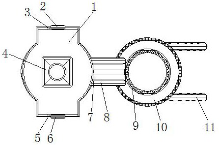
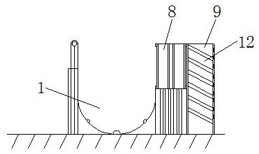
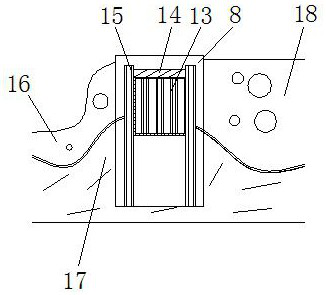
[0027] see Figure 1-5 , the present invention provides a technical solution: a side channel spillway for flood discharge from a reservoir, comprising a reservoir 1, a first gate 2, a water inlet 3, a supporting stone pillar 4, a water outlet 5, a second gate 6, an outlet channel 7, Overflow weir 8, buffer body 9, flood discharge area 10, discharge channel 11, flood discharge channel 12, fine sand 13, anti-seepage layer 14, pine pile 15, downstream area 18, ri...


PUM


Abstract

The invention relates to a reservoir flood discharge side channel type spillway. The reservoir flood discharge side channel type spillway comprises a water reservoir, a supporting stone pillar, an overflow weir, a flood discharge zone and an anti-seepage layer. A water inlet is formed in the top of the water reservoir. A first gate is arranged on the inner side of the water inlet. The supporting stone column is fixed in the water reservoir. A water outlet is formed in the bottom end of the water reservoir. A second gate is arranged on the inner side of the water outlet. The overflow weir is fixed to the outer wall of the water reservoir. A water outlet ditch is arranged on the inner side of the overflow weir. The flood discharge zone is connected to the right end of the overflow weir. A water drainage channel is formed in the right side of the flood discharge zone. A buffer body is arranged in the flood discharge zone. The reservoir flood discharge side channel type spillway has the beneficial effects that by arranging the water reservoir, the overflow weir, the water outlet ditch and the flood discharge zone, the left side of the water outlet ditch is vertically connected with theouter wall of the water reservoir, connectivity between the water outlet ditch and the water reservoir can be improved, and the situation that the water outlet ditch shakes during operation of the spillway, and normal operation of the spillway is affected is avoided.

Description

technical field [0001] The invention relates to the technical field of reservoir flood discharge devices, in particular to a side channel type spillway for reservoir flood discharge. Background technique [0002] With the development of science and technology and the progress of the social era, at present, newly-built reservoirs are gradually shifting to remote mountainous areas. Due to the steep slopes of river valleys, there are generally problems such as small dam heights and reservoirs, and large excavation volumes for spillways, and are suitable for side channel spillways. Topographical and geological conditions are easier to meet. [0003] During the use of the existing side channel spillway, the effect of flood discharge is not good, and seepage is prone to occur, which brings inconvenience to the device, and it is difficult to change the water flow, making the flood discharge work more difficult. Contents of the invention [0004] The purpose of the present invent...

Claims


Application Information

Patent Timeline
Patent Type & Authority Patents(China)
IPC IPC(8): E02B8/06
CPCE02B8/06
Inventor 焦宝治
Owner YUNNAN RUNJING WATER CONSERVANCY ELECTRIC POWER ENG TECH CO LTD
Learn More