Steel bar mechanical connecting piece and steel bar mechanical connecting method

A technology of mechanical connection and steel bars, which is applied in the direction of building components, building reinforcements, structural elements, etc., can solve the problems of affecting the tensile strength of steel bars, low tensile strength of steel bars, and high labor intensity

Inactive Publication Date: 2018-11-06
于洋
View PDF0 Cites 3 Cited by
  • Summary
  • Abstract
  • Description
  • Claims
  • Application Information

AI Technical Summary

Problems solved by technology

[0003] At present, the general steel bar connection methods in building construction include binding and lapping and welding. The operation of binding and lapping is complicated, the labor efficiency is low, and the labor intensity is high. The transportation is difficult, which seriously restricts the construction efficiency. The tensile strength of the steel bars after binding and lapping is low, which brings hidden dangers to the project quality; Problems seriously affect the tensile strength of the welded steel bars, and the welding process is complicated to operate on site and the construction cost is high
[0004] At present, there is still a mechanical connection method, which is to process the head parts of the two steel bars to be connected into threads respectively, and use a sleeve connector with internal threads to connect the two steel bars to be connected together through threads. This mechanical connection method needs to process all the heads of the steel bars that need to be connected into threads in advance, and then connect the two steel bars that need to be connected with the sleeve connector with internal threads through a rotating operation. The on-site operation workload is large. The labor intensity is high, and sometimes because the length of the screw thread of the sleeve connector is not enough, many connectors cannot meet the quality requirements in operation, causing serious quality problems

Method used


Image

  • Steel bar mechanical connecting piece and steel bar mechanical connecting method
  • Steel bar mechanical connecting piece and steel bar mechanical connecting method
  • Steel bar mechanical connecting piece and steel bar mechanical connecting method

Examples


Embodiment Construction

[0044] The present invention will be further described below in conjunction with the embodiments.

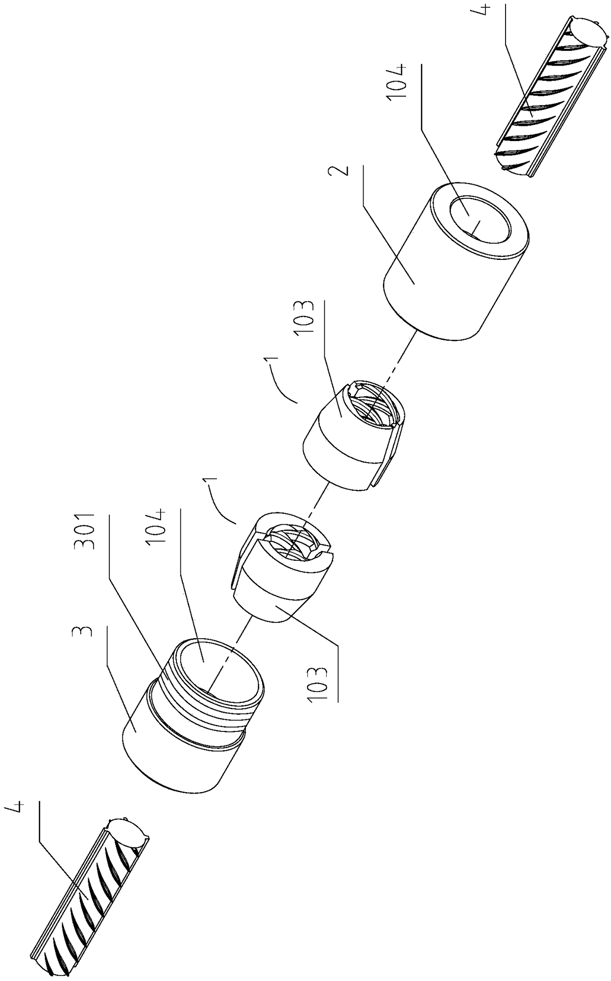
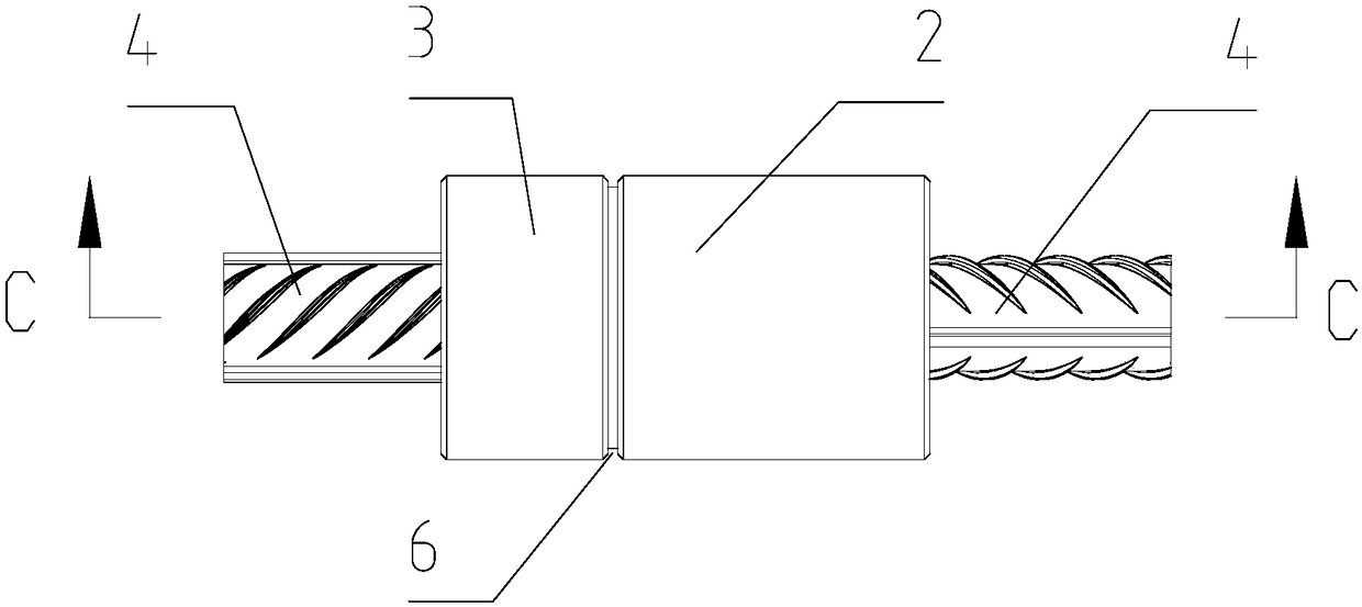
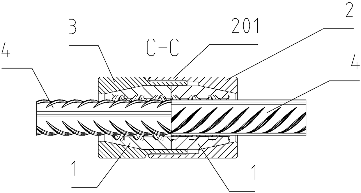
[0045] Figure 1-16 It is an embodiment of a steel bar mechanical connector of the present invention, which is provided with two clamps 1, and the two clamps 1 are respectively located on the left and right sides, and the clamp 1 is provided with a clamp inner Cavity 104, the clamp 1 can hold the steel bar 4 tightly in the inner cavity 104, the tail of the clamp 1 is provided with a locking outer cone surface 103; the outer circumference of the clamp 1 on the right is provided with The right clamp lock sleeve 2, the inside of the right clamp lock sleeve 2 is provided with a lock sleeve inner cavity 202, and one side of the right clamp lock sleeve inner cavity 202 is provided with a locking inner tapered surface 302, and the right clamp The locking inner cone surface 302 provided on one side of the inner cavity body 202 of the locking sleeve can hold the steel bar 4 tightly in t...


PUM


Abstract

The invention relates to a steel bar mechanical connecting piece and a steel bar mechanical connecting method. According to the steel bar mechanical connecting piece and the steel bar mechanical connecting method, the technical problems that existing steel bar connecting is unreliable in quality and cumbersome in operation are solved. The steel bar mechanical connecting piece is provided with twoembracing clamping hoops which are located on the left side and the right side correspondingly, embracing inner cavities are formed in the embracing clamping hoops, and steel bars can be embraced in the embracing inner cavities through the embracing clamping hoops; and locking outer conical surfaces are arranged at the tails of the embracing clamping hoops, anti-sliding buckling devices are arranged on the inner surfaces of the embracing inner cavities, anti-sliding buckling clamping grooves serve as the anti-sliding buckling devices, and the direction of the anti-sliding buckling clamping grooves is consistent with the direction of protruding patterns on the outer surfaces of the steel bars. The steel bar mechanical connecting piece can be widely used for mechanical connection of the building steel bars.

Description

technical field [0001] The invention relates to the field of construction machinery, in particular to a reinforcement mechanical connector and a reinforcement mechanical connection method. Background technique [0002] When building buildings and bridges in the construction industry, in order to meet the needs of high-rise buildings and bridges for steel skeletons, it is necessary to connect various specifications of rebar for use. [0003] At present, the general steel bar connection methods in building construction include binding and lapping and welding. The operation of binding and lapping is complicated, the labor efficiency is low, and the labor intensity is high. The transportation is difficult, which seriously restricts the construction efficiency. The tensile strength of the steel bars after binding and lapping is low, which brings hidden dangers to the project quality; The problem seriously affects the tensile strength of the welded steel bar, and the welding proc...

Claims


Application Information

Patent Timeline
Patent Type & Authority Applications(China)
IPC IPC(8): E04C5/16
CPCE04C5/162
Inventor 于小彭于洋
Owner 于洋
Why Eureka
Try Eureka