Exhaust pipe flexible joint structure

An exhaust pipe and flexible technology, applied in the field of flexible joints, can solve the problems of limited application, difficulty in arranging flexible joints, and loss of function, and achieve the effects of overcoming the narrow layout space, improving NVH effects, and increasing service life

Pending Publication Date: 2018-11-06
NINGBO KINROM IND
View PDF0 Cites 3 Cited by
  • Summary
  • Abstract
  • Description
  • Claims
  • Application Information

AI Technical Summary

Problems solved by technology

But there are also obvious weaknesses. When there is a break point in one of the knitted structures, the entire knitted structure will gradually spread out and lose its function, just like the common phenomenon of knitted stockings.
In addition, due to its large elastic range but poor supporting capacity, it cannot restrict the movement of the bellows in multiple directions. When large swings occur in all directions, the deformation range of the bellows cannot be limited and the bellows will easily break.
[0005] The other is the braided mesh structure. The braided mesh is usually made of multi-strand metal wires cross-woven in two directions. The appearance is relatively dense, so it can effectively protect the inner bellows. The gap between them is not easy to control, so the ability to suppress vibration is poor, and the application is limited
[0006] In addition, usually due to the large swing and vibration of the engine, the stress on the flexible joint is usually relatively large. In order to reduce the stress, the length of the flexible joint or the outer diameter of the flexible joint is usually increased, but the place where the flexible joint is arranged is usually The space is narrow, and the swing of the flexible joint easily interferes with surrounding parts, so it is difficult to arrange a flexible joint with a long length or a large outer diameter, which is another difficulty in the application of flexible joints

Method used


Image

  • Exhaust pipe flexible joint structure
  • Exhaust pipe flexible joint structure
  • Exhaust pipe flexible joint structure

Examples


Embodiment Construction

[0038] The invention will be further described in detail below in conjunction with the embodiments of the accompanying drawings.

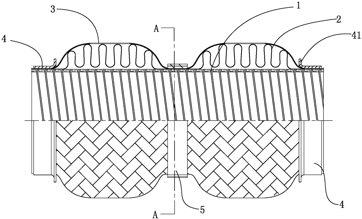
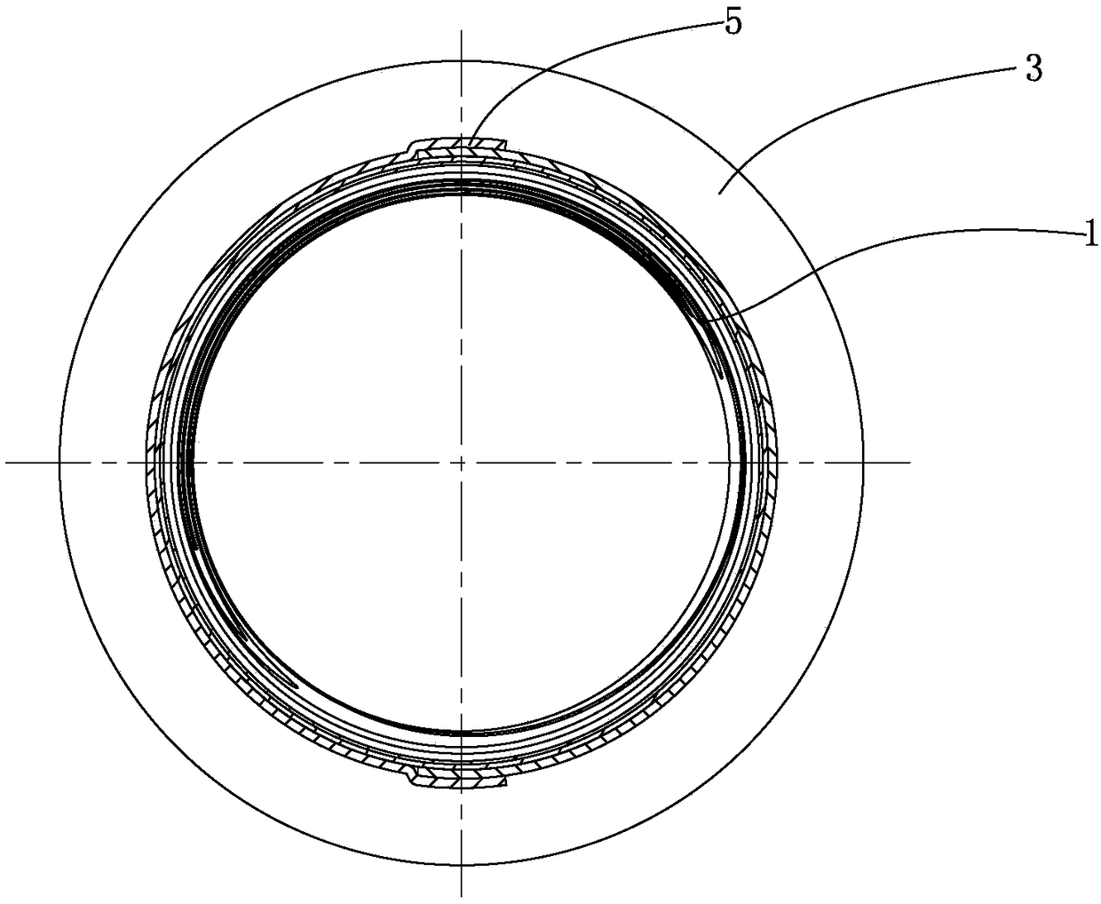
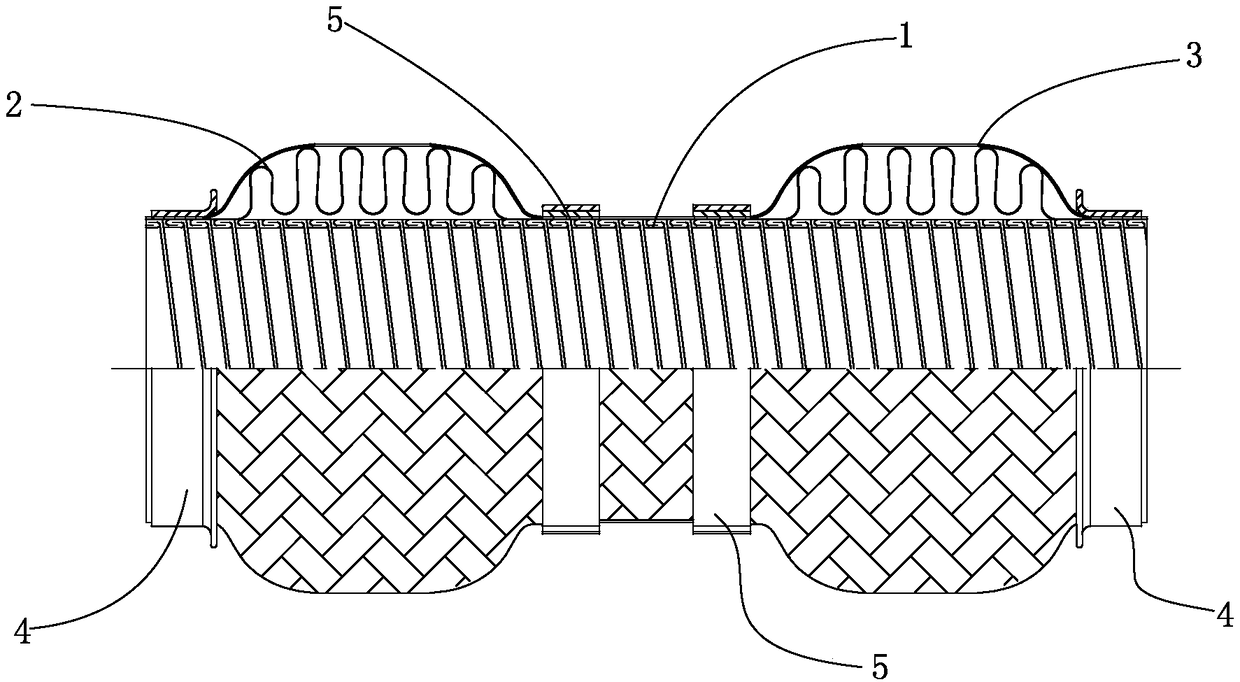
[0039] Such as Figure 1-2 As shown, it is a schematic diagram of the flexible joint structure of the exhaust pipe according to the first embodiment of the present invention. The flexible joint structure includes the inner inner pipe 1, the bellows 2 sleeved with the inner pipe 1, and the outer side of the bellows 2. The woven mesh 3 structure. The end of the inner tube 1 is fixedly connected to the end of the bellows 2, which can be compressed by internal expansion and external pressure and / or fixed by welding. The inner tube 1 is a buckle hose or braided network.

[0040] The braided net 3 has a segmented structure, and the length of each segment is less than or equal to 200mm. And the two ends of each segment of braided net 3 are fixedly connected with the bellows 2 through the fixing piece. Preferably, the corrugated pipe is also divided in...


PUM


Abstract

The invention relates to an exhaust pipe flexible joint structure. The exhaust pipe flexible joint structure is mainly used in a vehicle exhaust pipe structure, and comprises a corrugated pipe and braided meshes, wherein the corrugated pipe and the braided meshes are coaxially arranged in sequence from inside to outside in a sleeving mode; and the exhaust pipe flexible joint structure is characterized by comprising at least two sections of the braided meshes, moreover, the two ends of each section of the braided mesh are fixedly connected with the corrugated pipe on the inner side through fixing pieces, and the length of each section of braided mesh is smaller than or equal to 200 mm. According to the exhaust pipe flexible joint structure, a better damping effect is achieved, the NVH effect of the whole vehicle is improved; moreover, in a transverse-engine front-drive automobile, when relatively large swing occurs in the front row of an exhaust system, the shearing deformation of the corrugated pipe inside can be converted into bending deformation through the tightly-attached braided meshes, in an longitudinal-engine rear-drive automobile, when the front row of the exhaust system rotates, the braided meshes can well share a part of the torque, then the stress of the corrugated pipe inside is greatly reduced, and the service life of the corrugated pipe inside is prolonged.

Description

technical field [0001] The invention relates to the technical field of automobiles, in particular to a flexible joint used on the exhaust system of an automobile engine. Background technique [0002] Flexible joints for placement in the exhaust system of a car engine. One end of the exhaust system is connected to the engine, and the other end is connected to the underbody of the vehicle body. The engine generates vibration and vibration, which will be transmitted to the vehicle body through the exhaust system, which will have a bad impact on the comfort of the ride. At the same time, the vehicle will The body vibration generated on rough roads will be transmitted to the front section of the exhaust system, manifold and engine through the exhaust system, which also has an adverse effect on NVH and durability. [0003] In order to improve the above problems, a flexible joint is usually placed at the connection between the exhaust system and the engine manifold to block two-wa...

Claims


Application Information

Patent Timeline
Patent Type & Authority Applications(China)
IPC IPC(8): F01N13/08F01N13/18
CPCF01N13/08F01N13/1811F01N13/1816F16L27/1004F16L27/111F01N2450/22F01N2470/12
Inventor 董菁荣
Owner NINGBO KINROM IND
Why Eureka
Try Eureka