Asymmetrical wedge-shaped vortex generator applied to flow control over compressor cascade and design method thereof
A vortex generator and cascade flow technology, applied in mechanical equipment, gas turbine devices, machines/engines, etc., can solve the problems of inability to efficiently reduce compressor flow loss, unreasonable structure, and weak compressor flow loss, etc. The effect of low total pressure loss, reduced airflow separation, and reduced form resistance loss
- Summary
- Abstract
- Description
- Claims
- Application Information
AI Technical Summary
Problems solved by technology
Method used
Image

Examples
Embodiment Construction
[0026] Embodiments of the present invention are described in detail below, and the embodiments are exemplary and intended to explain the present invention, but should not be construed as limiting the present invention.
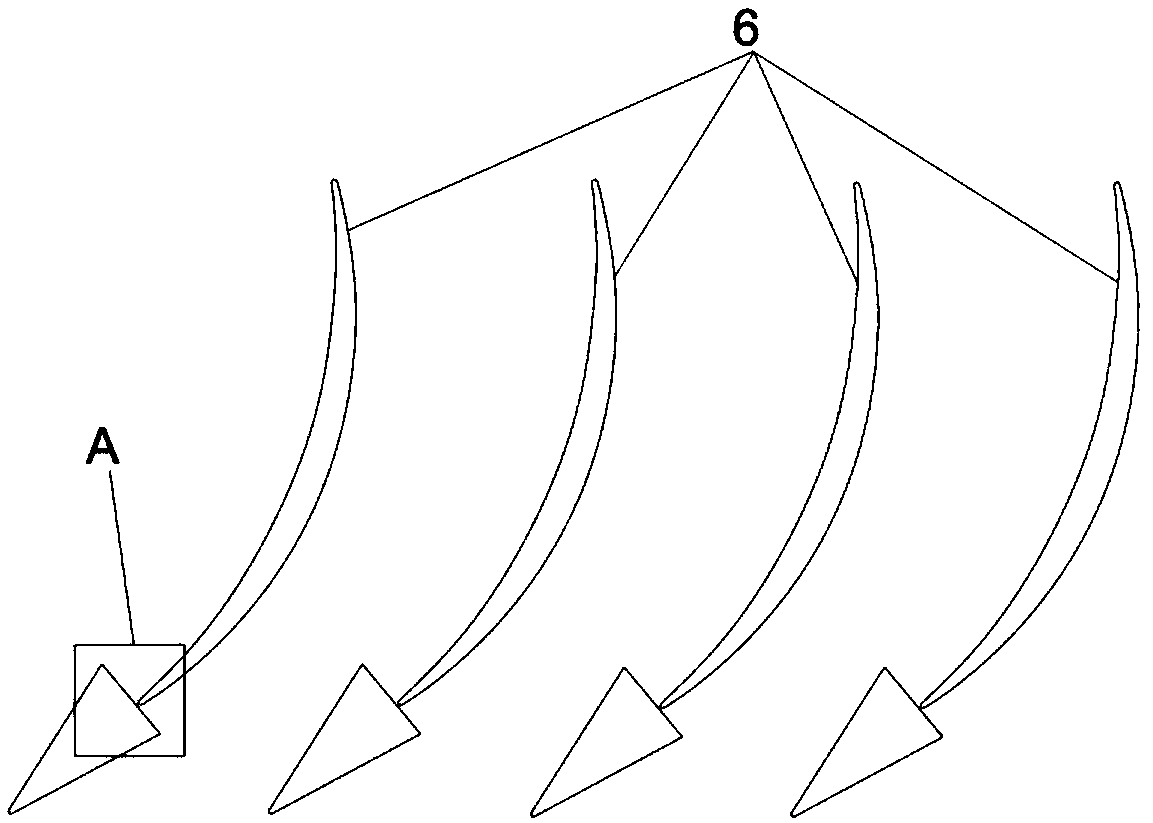
[0027] An asymmetric wedge-shaped vortex generator method applied to flow control of a compressor cascade in this embodiment includes the following steps:
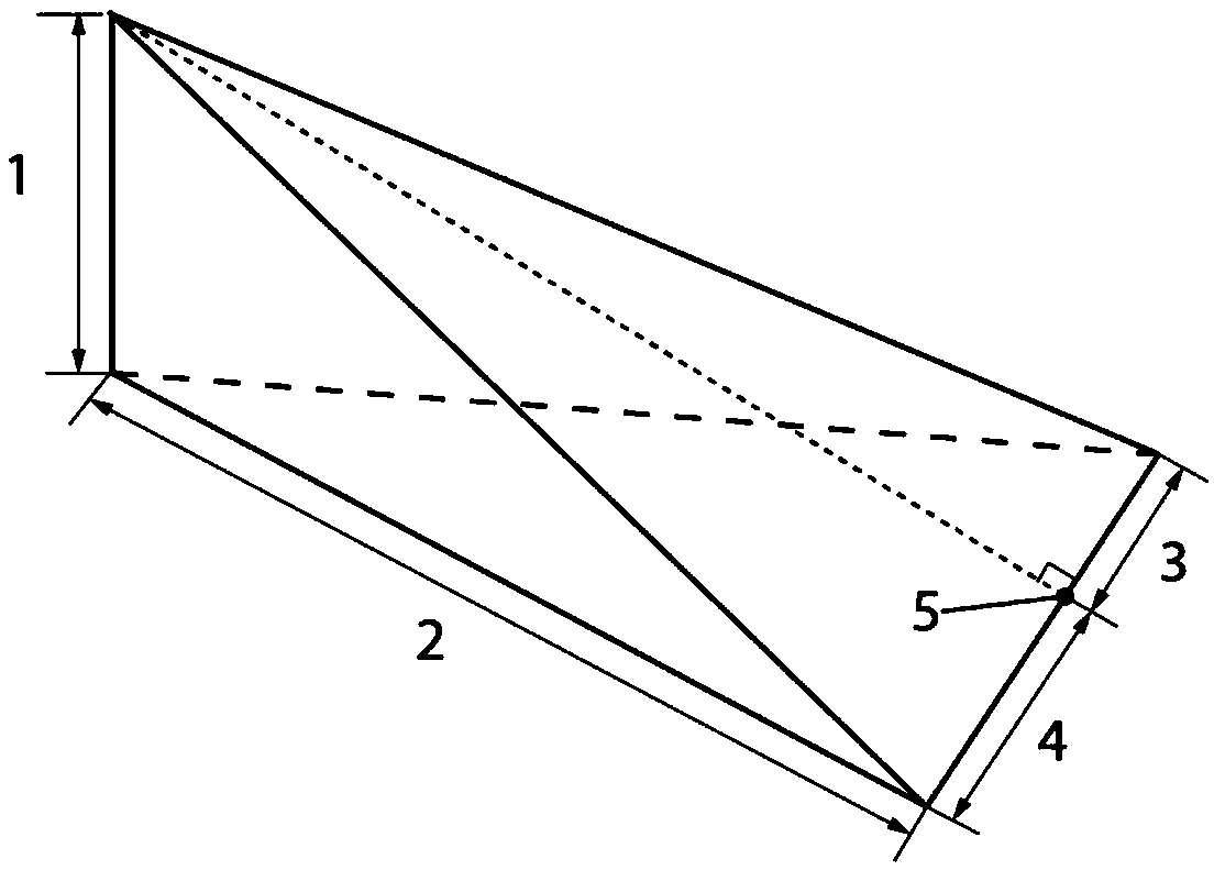
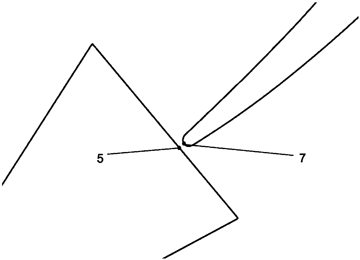
[0028] Step 1: Determine the design parameters of the geometric structure of the wedge-shaped vortex generator as radial height, axial length, suction side width and pressure side width. refer to figure 1 , the asymmetric wedge-shaped vortex generator has a tetrahedral structure as a whole. The geometric dimensions are determined by radial height 1, axial length 2, suction side width 3, and pressure side width 4. 5 is the vertical point of the bottom edge of the triangle on the top surface of the asymmetric wedge-shaped vortex generator. The radial height 1 is perpendicular to the bottom end wall.
[0...
PUM
| Property | Measurement | Unit |
|---|---|---|
| Radial height | aaaaa | aaaaa |
| Axial length | aaaaa | aaaaa |
Abstract
Description
Claims
Application Information
PatSnap Eureka turns technology decisions into work you can execute. Powered by our Innovation Knowledge Graph, it runs expert workflows across engineering, life sciences, materials and intellectual property. Get your review-ready output in minutes.


