Engine starting circuit

An engine starting and engine technology, which is applied to the starting of the engine, the starting of the engine with the motor, the ignition of the engine, etc., can solve the problems of unsmooth starting, instability, and low engine speed, and achieve the effect of convenient use.

Pending Publication Date: 2018-11-06
SUZHOU CLEVA PRECISION MACHINERY & TECH
0 Cites 0 Cited by

AI-Extracted Technical Summary

Problems solved by technology

A magneto is a small alternator that generates a magnetic field through a permanent magnet, but at the initial stage of starting a gasoline engine, the voltage supplied by the magneto is low and unstable due to the...

Method used

(3) A preset time can be set in the electronic control circuit 4. In the engine starting stage, the DC power supply circuit 3 is connected and starts to ignite the spark plug 10, and starts timing. After reaching the preset time, it is judged that the engine It has been working normally; in this embodiment, the preset time is 2 s to 5 s; in this embodiment, by setting the preset time, the preset time is determined through experience and engine performance, so as to switch directly, and the realization is relatively simple .
(3) A preset time can be set in the electronic control circuit 4. In the engine starting stage, the DC power supply circuit 3 is connected and starts to ignite the spark plug 10, and starts timing. After reaching the preset time, it is judged that the engine It has been working normally; in this embodiment, the preset time is 2s to 5s; in this embodiment, by setting the preset time, the preset time is determined through experience and engine performance, so as to switch directly, and the realization is relatively simple;
In the first embodiment of the present invention, as shown in Figure 1, described ignition circuit 1 comprises the first primary coil 11 that is connected with magneto circuit 2, the second one that is connected with DC power supply circuit 3 The primary coil 12, and the secondary coil 13 connected with the spark plug 10. The n...

Abstract

The invention discloses an engine starting circuit. The engine starting circuit is used for providing enough voltage for ignition of a spark plug when the engine is started and works; the engine starting circuit comprises an ignition circuit, a magnetic motor circuit, a direct-current electrical source circuit, an electronic control circuit, a switching circuit, and a starting motor circuit, wherein the ignition circuit is used for boosting the voltage accessed to the ignition circuit to the ignition voltage of a spark plug; the magnetic motor circuit is connected with the ignition circuit through a first switch; the direct-current electrical source circuit comprises a direct-current electrical source and a second switch, and the direct-current electrical source is connected with the ignition circuit through the second switch; the electronic control circuit is used for acquiring the working state of the engine and sending out a control signal; the switching circuit is used for receiving the control signal and controlling the connect or the disconnect of the direct-current electrical source circuit and the magnetic motor circuit by controlling the on-off of the first switch and thesecond switch; the starting motor circuit comprises a starting motor, wherein the starting motor is installed on the engine, the starting motor circuit is connected with the electronic control circuitand receives the control signal so as to control starting or stopping of a motor.

Application Domain

Internal combustion piston enginesElectric motor starters +2

Technology Topic

Spark plugIgnition voltage +5

Image

  • Engine starting circuit
  • Engine starting circuit
  • Engine starting circuit

Examples

  • Experimental program(1)

Example Embodiment

[0036] In order to enable those skilled in the art to better understand the technical solutions in the present invention, the technical solutions in the embodiments of the present invention will be clearly and completely described below in conjunction with the drawings in the embodiments of the present invention. Obviously, the described The embodiments are only some of the embodiments of the present invention, not all of them. Based on the embodiments of the present invention, all other embodiments obtained by persons of ordinary skill in the art without making creative efforts shall fall within the protection scope of the present invention.
[0037] Furthermore, repeated reference numerals or designations may be used in different embodiments. These repetitions are merely for the sake of simplicity and clarity of describing the present invention, and do not imply any relationship between the different embodiments or structures discussed.
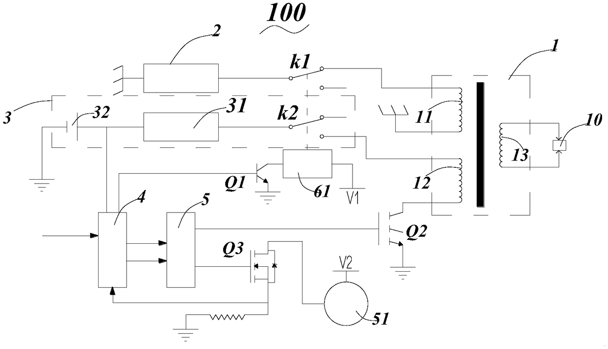
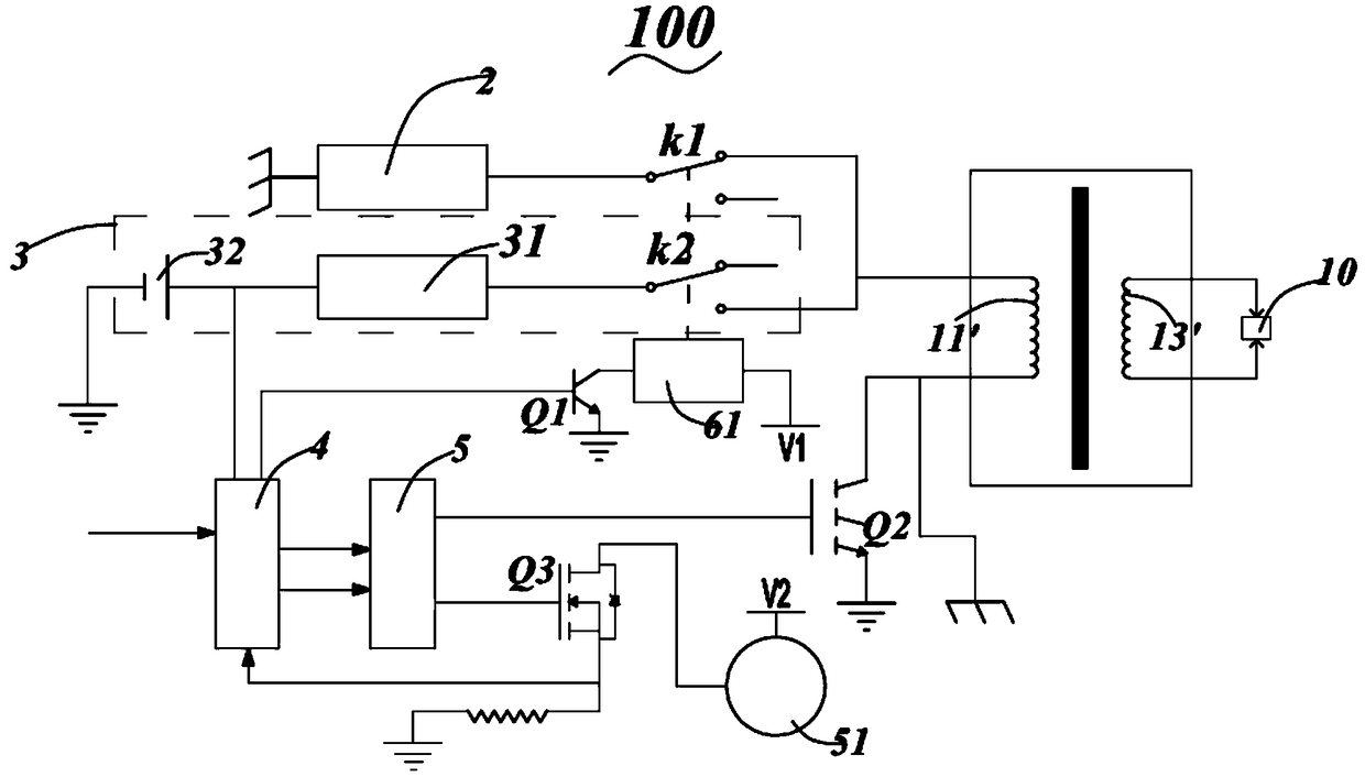
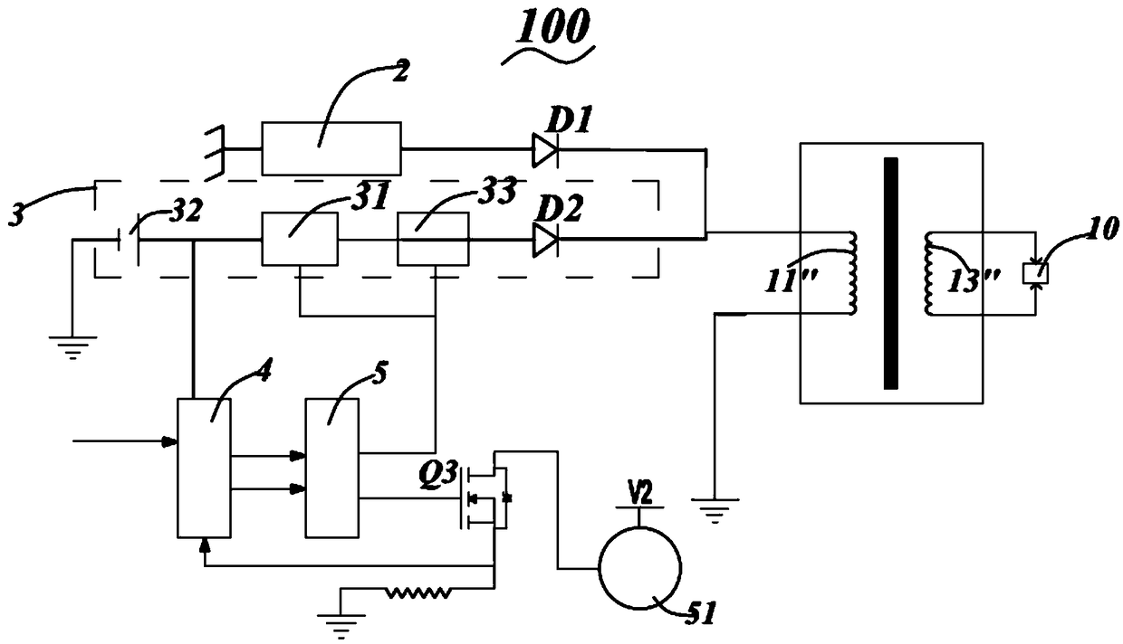
[0038] like Figure 1 to Figure 3 As shown, the present invention provides an engine starting circuit 100 for providing sufficient voltage for the spark plug 10 to ignite when the engine starts and works. The engine starting circuit 100 includes:
[0039] The ignition circuit 1 is used to increase the voltage connected to the ignition circuit 1 to the ignition voltage of the spark plug 10; the ignition voltage of the spark plug 10 usually needs to reach tens of thousands of volts, and the directly obtainable voltage cannot reach such a high level, so an ignition circuit is necessary 1 for boosting;
[0040] The magneto circuit 2 is connected to the ignition circuit 1, the magneto circuit 2 includes a magneto, and the magneto is a small alternator utilizing permanent magnets;
[0041] The DC power supply circuit 3 includes a DC power supply 32, and the DC power supply 32 is connected to the ignition circuit 1; in this embodiment, the DC power supply circuit 3 also includes a boost circuit 31, and the boost circuit 31 is connected to the DC Between the power supply 32 and the ignition circuit 1, the DC power supply 32 is boosted for the first time, and the ignition circuit 1 further boosts the boosted DC power supply for the second time; in this embodiment, the DC power supply 32 is about is 7.2 V, after the first step-up of the booster circuit 31, it can reach about 200 V, and then after the second step-up of the ignition circuit 1, it can reach tens of thousands of volts;
[0042] The starter motor circuit includes a starter motor 51 installed on the engine, and the starter motor 51 is connected with the flywheel shaft or crankshaft of the engine through a reduction mechanism and a clutch mechanism. At the initial stage of starting the engine, the starter motor 51 drives the flywheel to rotate to assist engine work;
[0043] In the engine starting phase, the starter motor 51 works to help the engine start, and the magneto circuit 2 fails, and the DC power supply circuit 3 is turned on for spark plug ignition;
[0044] In the normal working stage of the engine, the starter motor 51 stops working, the DC power supply circuit 3 fails, and the magneto circuit 2 is turned on for the spark plug to ignite.
[0045]The engine starting circuit 100 also includes: an electronic control circuit 4, used to obtain the working state of the engine and send a control signal, the starter motor circuit is connected to the electronic control circuit 4 and receives the control signal to control the starter motor 51 start and stop.
[0046] Specifically, such as figure 1 and figure 2 As shown, the magneto circuit 2 is connected to the ignition circuit 1 through the first switch k1, the DC power supply circuit 3 also includes a second switch k2, and the DC power supply 32 is connected to the ignition circuit 1 through the second switch k2, so The engine starting circuit 100 also includes a switch circuit, the switch circuit receives the control signal and controls the opening and closing of the first switch k1 and the second switch k2 to control the connection or disconnection of the DC power supply circuit 3 and the magneto circuit 2, and , when the engine is started, the second switch k2 is closed and the first switch k1 is opened; after the engine works normally, the first switch k1 is closed and the second switch k2 is opened.
[0047] In the engine starting stage, the electronic control circuit 4 controls the starter motor 51 to work to assist the engine start, and the switching circuit controls the second switch k2 to close and the first switch k1 to open, and the DC power supply circuit 3 conduction for the spark plug 10 to ignite;
[0048] In the normal working phase of the engine, the electronic control circuit 4 controls the starter motor 51 to stop working, and the switching circuit controls the first switch k1 to be closed, the second switch k2 to be opened, and the magneto circuit 2 to be turned on for Spark plug 10 fires. Since the magneto can generate alternating current, it also has a corresponding frequency, and ignites the spark plug 10 .
[0049] Further, the switching circuit includes an electromagnet 61 and a first switching element Q1 for controlling the on-off of the electromagnet 61, the first switching element Q1 includes a first control terminal, and the control signal includes a switching signal; A control terminal is connected to the electronic control circuit 4 to receive a switching signal to control the first switch element Q1 to be turned on or off, so as to realize the electromagnet 61 to be turned on or off.
[0050] Specifically, the switching circuit also includes a first power supply V1, and the first switching element Q1 also includes a first input terminal and a first output terminal, the first output terminal is grounded, and one terminal of the electromagnet 61 is connected to the first One input end is connected, and the other end is connected with the first power supply V1, and the first power supply V1 is direct current. In this embodiment, when the first control terminal of the first switching element Q1 does not receive the switching signal, the first switching element Q1 is turned on, and the electromagnet 61 is energized; the first control terminal receives the switching signal , the first switching element Q1 is turned off, and the electromagnet 61 is powered off. In this embodiment, since the current required to make the electromagnet 61 work is relatively small, the first switching element Q1 is a triode.
[0051] In addition, in this embodiment, the first switch k1 and the second switch k2 are single-pole double-throw switches, and one end is connected to the circuit, and the other end is suspended, and the electromagnet 61 is close to the first switch k1 and the second switch k2. The second switch k2 is set; and, when the electromagnet 61 is energized, the first switch k1 is disconnected, and the second switch k2 is connected; when the electromagnet 61 is powered off, the first switch k1 is connected, and the second switch k1 is connected. The second switch k2 is turned off. Therefore, the magneto circuit 2 and the DC power supply circuit 3 can be controlled by the on-off condition of the electromagnet 61 .
[0052] That is, when the first control terminal does not receive a switching signal, the first switch element Q1 is turned on, the electromagnet 61 is turned on, the first switch k1 is turned off, the second switch k2 is turned on, and the DC power supply circuit 3 is turned on. for spark plug 10 to ignite;
[0053] When the first control terminal receives the switch signal, the first switch element Q1 is turned off, the electromagnet 61 is powered off, the first switch k1 is connected, the second switch k2 is turned off, and the magnetic power supply circuit is turned on for the spark plug 10 ignition.
[0054] In addition, the electromagnet 61, the first switch k1, and the second switch k2 in the switching circuit are equivalent to a structure that constitutes a relay. Therefore, if a relay is directly used to replace the above-mentioned first switch k1, second switch k2, and Electromagnet 61, then also can reach the purpose of the present invention.
[0055] Further, the ignition circuit 1 includes a second switch element Q2, and the second switch element Q2 is connected with the DC power supply circuit 3 to control the ignition frequency of the DC power supply 32 for igniting the spark plug 10 . The second switching element Q2 includes a second control terminal, the control signal includes an ignition frequency signal, and the second control terminal is connected to the electronic control circuit 4 to receive the ignition frequency signal and control the conduction or activation of the second switching element Q2. disconnect. The second switching element Q2 can convert the direct current into a current with a specific frequency by controlling the ignition frequency.
[0056] The second switch element Q2 also includes a second input terminal and a second output terminal, the second input terminal is grounded, and the second output terminal is connected to the DC power supply circuit 3 through the ignition circuit 1 . Therefore, the ignition frequency signal received by the second control terminal can control the conduction or disconnection of the second switch element Q2, thereby controlling the ignition frequency of the DC power supply 32 for ignition. The electronic control circuit 4 obtains the working state and various parameters of the engine, and analyzes them to obtain the ignition frequency, and outputs the ignition frequency signal to the second switch element Q2.
[0057] In addition, since the ignition frequency signal has a certain frequency and makes the second switching element Q2 continuously open and close, the DC power supply circuit 3 also changes at the above frequency, thereby changing the ignition frequency of the spark plug 10 .
[0058] In this embodiment, the second switching element Q2 is connected to the DC power supply circuit through the ignition circuit 1 and is set independently from the ignition circuit 1. Of course, if the second switching element Q2 is integrated in the ignition circuit 1, or connected in the DC power supply circuit 3, then the purpose of the present invention can also be achieved.
[0059] Further, the starter motor circuit includes a starter motor 51, and a third switch element Q3 for controlling the on-off of the starter motor 51, the third switch element Q3 includes a third control terminal, and the control signal includes a motor control signal; The third control terminal is connected to the electronic control circuit 4 to receive the motor control signal and control the third switching element Q3 to be turned on or off. The starter motor 51 is usually installed on the engine, and before the engine works normally, the flywheel of the engine is assisted and driven to make it rotate, thereby reducing the trouble of manpower starting the engine. Therefore, after the engine works normally, the starter motor 51 can be turned off.
[0060] The electronic control circuit 4 is connected with the starter motor 51 to obtain the feedback of the working state of the starter motor 51, so as to judge the switching time, ignition timing or ignition frequency, etc.
[0061] Specifically, the third switching element Q3 also includes a third input terminal and a third output terminal, the starter motor circuit also includes a second power supply V2, the third input terminal is connected to the starter motor 51, and the starter motor 51 is connected to the second power supply V2; the third output terminal is grounded and connected to the electronic control circuit 4 at the same time. When the third switch element Q3 is turned on, the starter motor 51 starts; when the third switch element Q3 is turned off, the starter motor 51 stops working. The second power source V2 is a direct current, and the second power source V2 is independent from the first power source V1, of course, they can also be the same current source.
[0062] In this implementation manner, the third switching element Q3 is a MOS transistor. This is because a larger current is required to allow the starter motor 51 to work, so a MOS tube is used.
[0063] Therefore, before the engine is started, the starter motor 51 is started to work to boost the engine and drive the flywheel of the engine to rotate, and at the same time, the spark plug 10 is ignited through the DC power supply 32 . The DC power supply 32 is more stable than the magneto power supply, thereby ensuring that the ignition energy is stable within a relatively large range and ensuring that the spark plug 10 can ignite successfully. The engine works normally, and then switches to the magneto circuit 2, so that the engine can work normally and stably.
[0064] In addition, the engine starting circuit 100 also includes a drive circuit 5, the drive circuit 5 is connected between the electronic control circuit 4 and the starter motor circuit, and outputs a motor control signal to the starter motor circuit; the drive circuit 5 It is also connected between the electronic control circuit 4 and the second switching element Q2, and outputs an ignition frequency signal to the second switching element Q2.
[0065] In the first embodiment of the present invention, as figure 1 As shown, the ignition circuit 1 includes a first primary coil 11 connected to the magneto circuit 2 , a second primary coil 12 connected to the DC power supply circuit 3 , and a secondary coil 13 connected to the spark plug 10 . The number of turns of the secondary coil 13 is much larger than that of the first primary coil 11 and the second primary coil 12, so as to achieve the boosting effect. In this embodiment, one end of the first primary coil 11 is connected to the magneto circuit 2, and the other end is grounded; one end of the second primary coil 12 is connected to the DC power supply circuit 3, and the other end is connected through the second switching element Q2 and ground. In this embodiment, the ground terminal of the first primary coil 11 and the ground terminal of the second primary coil 12 may or may not be insulated from each other.
[0066] In the second embodiment of the present invention, such as figure 2 As shown, the ignition circuit 1 includes a primary coil 11' connected to both the magneto circuit 2 and the DC power supply circuit 3 and a secondary coil 13' connected to the spark plug 10, that is, one end of the primary coil 11' It is connected to both the magneto circuit 2 and the DC power supply circuit 3, and the other end is grounded. The primary coil 11' has two ground terminals, namely a DC power supply ground terminal and a magneto ground terminal, and the DC power supply ground terminal and the magneto ground terminal are insulated from each other. In actual operation, usually the ground terminal of the magneto is connected to the outer casing, and the ground terminal of the DC power supply is insulated from the casing.
[0067] In the first embodiment and the second embodiment, at the engine starting stage, the electronic control circuit 4 controls the starter motor 51 to work to assist the engine start, and at the same time sends an ignition frequency signal to control the conduction and switching of the second switching element Q2. Disconnect to control the ignition frequency of the DC power supply 32;
[0068] After judging that the engine is working normally, the electronic control circuit 4 sends a switch signal to the switch element Q1, the first switch k1 is connected, and the second switch k2 is turned off;
[0069] In the normal working stage of the engine, the electronic control circuit 4 controls the starter motor 51 to stop working, and the switch k1 is connected, and the magneto power supply circuit works.
[0070] It should be noted that, in the engine starting stage, the engine is not working normally, and the electronic control circuit 4 cannot obtain the signal of the normal operation of the engine, and correspondingly cannot send a switching signal; The circuit 4 obtains the signal of the normal operation of the engine, and at the same time sends out the switching signal accordingly. Therefore, it is necessary to judge when the engine has been in normal operation. The following are three judgment methods:
[0071] (1) The working state of the starter motor 51 can be fed back to the electronic control circuit 4. The electronic control circuit 4 monitors the current of the starter motor 51. When the current of the starter motor 51 is less than the threshold current and keeps this state for a few seconds, then Judging that the engine has been working normally; in this embodiment, the threshold current is 5A;
[0072] (2) The working state of the engine can be fed back to the electronic control circuit 4, and the electronic control circuit 4 can judge that the engine is working normally when the engine speed is greater than the threshold speed and keeps the state for a few seconds by monitoring the engine speed; In this embodiment, the threshold speed is 1500 r/min;
[0073](3) A preset time can be set in the electronic control circuit 4. During the engine starting stage, the DC power supply circuit 3 is connected and the spark plug 10 is ignited, and the timing is started. After the preset time is reached, it is judged that the engine is working normally ; In this embodiment, the preset time is 2 s to 5 s; in this embodiment, by setting the preset time, the preset time is determined through experience and engine performance, so as to directly switch, and the implementation is relatively simple.
[0074] All the above three methods can realize the judgment of the working state of the engine. Of course, if there are other judgment methods, as long as the effect of reasonably judging the engine state can be achieved, the purpose of the present invention can be achieved.
[0075] In the third embodiment of the present invention, such as image 3 As shown, the magneto circuit 2 is connected to the ignition circuit 1 through the first diode D1, the DC power supply circuit 3 also includes a second diode D2, and the DC power supply 32 is connected to the ignition circuit 1 through the second diode D2. Into the ignition circuit 1; in this embodiment, the DC power supply circuit 3 further includes an ignition control circuit 33 to control the ignition frequency, and the ignition control circuit 33 is connected between the DC power supply 32 and the second diode D2. Of course, in this embodiment, a boost circuit 31 is also provided to boost the DC power supply 32 for the first time.
[0076] In the engine starting stage, the electronic control circuit 4 controls the starter motor 51 to work to assist the engine starting. Since the voltage of the DC power supply 32 is higher than the voltage generated by the magneto circuit 2, the second diode D2 is turned on, and the first The diode D1 is disconnected, and the circuit of the DC power supply 32 works for the spark plug to ignite;
[0077] After judging that the engine has worked normally, the electronic control circuit 4 sends a switching signal to the boost circuit 31, and the boost circuit 31 fails;
[0078] In the normal working stage of the engine, the electronic control circuit 4 controls the starter motor 51 to stop working. Since the voltage of the DC power supply 32 is lower than the voltage generated by the magneto circuit 2, the first diode D1 is turned on, and the second diode D1 is turned on. Tube D2 is open and the magneto power circuit operates for spark plug firing.
[0079] The ignition circuit 1 includes a primary coil 11'' connected to both the magneto circuit 2 and the DC power supply circuit 3, and a secondary coil 13'' connected to a spark plug. The other end of the primary coil 11'' directly to ground.
[0080] In the third embodiment, there are four ways to determine that the engine starts normally, which will be described in detail below:
[0081] (1) The working state of the starter motor 51 can be fed back to the electronic control circuit 4. The electronic control circuit 4 monitors the current of the starter motor 51. When the current of the starter motor 51 is less than the threshold current and keeps this state for a few seconds, then Judging that the engine has been working normally; in this embodiment, the threshold current is 5A;
[0082] (2) The working state of the engine can be fed back to the electronic control circuit 4, and the electronic control circuit 4 can judge that the engine is working normally when the engine speed is greater than the threshold speed and keeps the state for a few seconds by monitoring the engine speed; In this embodiment, the threshold speed is 1500r/min;
[0083] (3) A preset time can be set in the electronic control circuit 4. During the engine starting stage, the DC power supply circuit 3 is connected and the spark plug 10 is ignited, and the timing is started. After the preset time is reached, it is judged that the engine is working normally ; In this embodiment, the preset time is 2s to 5s; In this embodiment, by setting the preset time, the preset time is determined through experience and engine performance, so as to directly switch, and the realization is relatively simple;
[0084] (4) The power supply voltage of the DC power supply circuit 3 can be fed back to the electronic control circuit 4. When the electronic control circuit 4 detects that the power supply voltage of the DC power supply circuit within at least three ignition cycles is lower than the voltage generated by the magneto circuit 2, that is It means that when the DC power supply circuit is not discharged, it is judged that the engine has started normally.
[0085] The above four methods can realize the judgment of the working state of the engine. Of course, if there are other judgment methods, as long as the effect of reasonably judging the engine state can be achieved, the purpose of the present invention can be achieved.
[0086] In summary, the engine starting circuit 100 is generally used in gasoline engines, and has two working states: when the engine starts to start, it is driven by a DC power supply 32 to ensure that the spark plug 10 can obtain sufficient ignition voltage; It can start normally even under low temperature and cold engine state; after the engine works normally, it will switch to magneto voltage drive, which is more environmentally friendly and energy-saving. Therefore, it is convenient for users to use.
[0087] It should be understood that although the description is described according to the embodiments, not each embodiment only includes an independent technical solution, and this description of the description is only for clarity, and those skilled in the art should take the description as a whole, and each The technical solutions in the embodiments can also be properly combined to form other embodiments that can be understood by those skilled in the art.
[0088] The series of detailed descriptions listed above are only specific descriptions of feasible embodiments of the present invention, and are not intended to limit the scope of protection of the present invention. All equivalent embodiments or changes made without departing from the technical spirit of the present invention All should be included within the protection scope of the present invention.

PUM

no PUM

Description & Claims & Application Information

We can also present the details of the Description, Claims and Application information to help users get a comprehensive understanding of the technical details of the patent, such as background art, summary of invention, brief description of drawings, description of embodiments, and other original content. On the other hand, users can also determine the specific scope of protection of the technology through the list of claims; as well as understand the changes in the life cycle of the technology with the presentation of the patent timeline. Login to view more.

Similar technology patents

Macrocyclic picolinamides as fungicides

ActiveUS20140187588A1good performanceeasy to use
Owner:CORTEVA AGRISCIENCE LLC

System and method of monitoring temperature

InactiveUS7140768B2less susceptible to tampereasy to use
Owner:COLD CHAIN TECH

Wireless charging transmitter, receiver, charging device and wireless charging method

ActiveCN104158269ASimple codingeasy to use
Owner:湖南长城科技信息有限公司 +1

Classification and recommendation of technical efficacy words

  • easy to use

Laser assisted total joint arthroplasty

InactiveUS20090234360A1easy to use
Owner:ALEXANDER VLADIMIR

Enclosure for a portable hemodialysis system

ActiveUS20090114582A1easy to use
Owner:DEKA PROD LLP
Why Eureka
Try Eureka