Variable damping shock absorber

A shock absorber and damping technology, used in shock absorbers, springs/shock absorbers, shock absorbers, etc., can solve the problems of high failure rate, high cost and short service life of solenoid valves, and achieve high comfort and safety. The effect of safety, small impact force of liquid flow and long service life

Pending Publication Date: 2018-11-06
XGM CORP LTD
View PDF1 Cites 1 Cited by
  • Summary
  • Abstract
  • Description
  • Claims
  • Application Information

AI Technical Summary

Problems solved by technology

[0004] However, the reliability of the existing shock absorber products with adjustable damping has been criticized by consumers, especially the related throttling elements are easily damaged due to excessive liquid flow impact pressure, and the service life is short
Also, see Figure 9 , the housing of the electromagnetic valve on the existing variable damping shock absorber is usually connected by riveting at point A by the inner tube and the outer tube. In order to ensure the sealing performance, argon arc welding is required at point A, and the manufacturing process is expensive. The cost is high, and in order to ensure the concentricity of the inner tube and the outer tube and the liquid flow performance on both sides of the inner tube, several bosses are formed on the inner tube by stamping, and the positioning is realized by the cooperation between the bosses and the outer tube. A liquid flow channel is formed between the pipe and the outer pipe; the solenoid valve in the electronic compound damping device disclosed in the Chinese invention patent CN 107869545 A adopts a traditional shell structure, but production practice shows that the inner and outer pipes are concentric The accuracy is difficult to guarantee, and the quality is unstable, resulting in easy damage to the solenoid valve shell, and a high failure rate of the solenoid valve

Method used


Image

  • Variable damping shock absorber
  • Variable damping shock absorber
  • Variable damping shock absorber

Examples


Embodiment Construction

[0027] The present invention will be further described below in conjunction with the accompanying drawings.

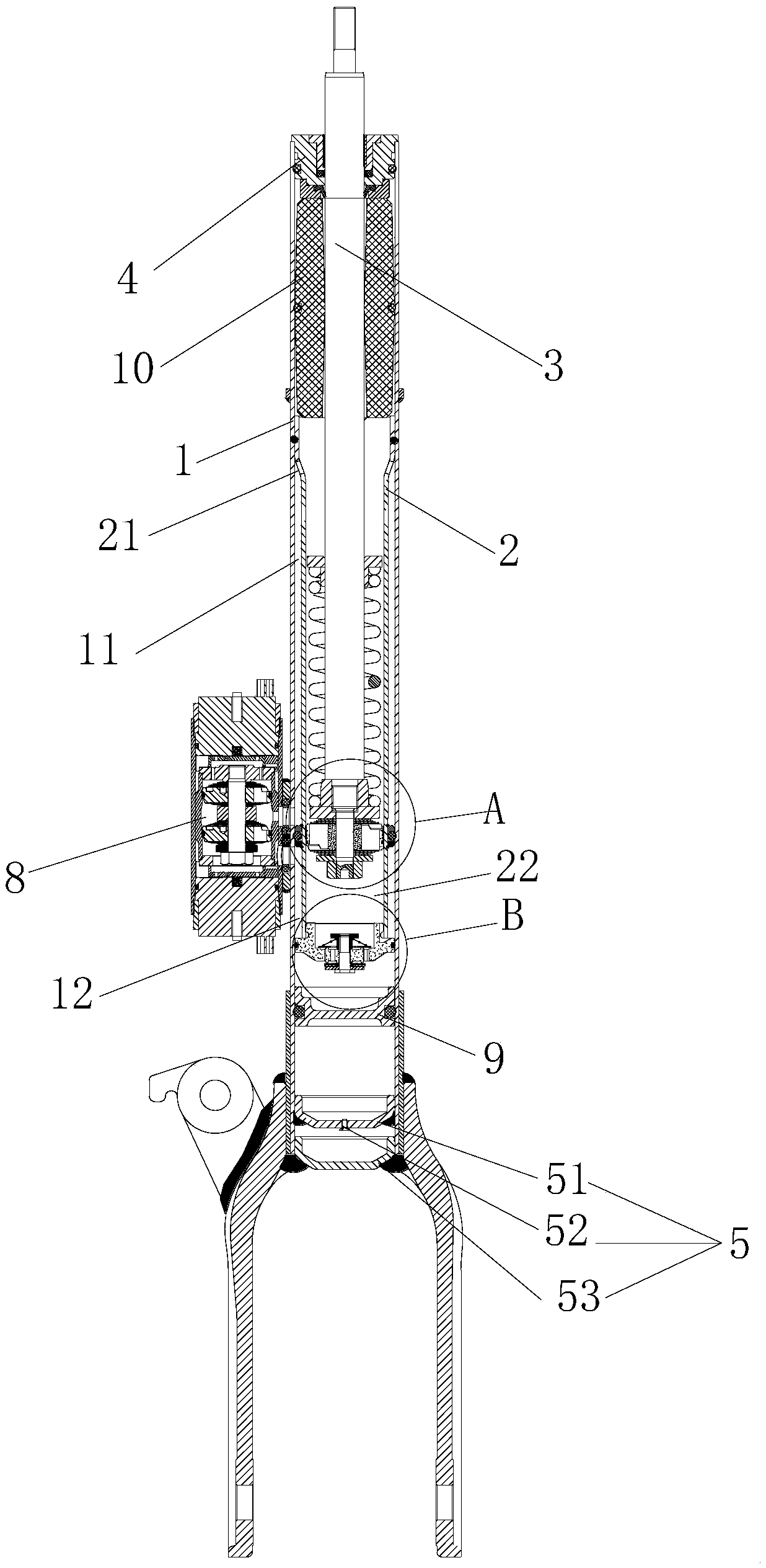
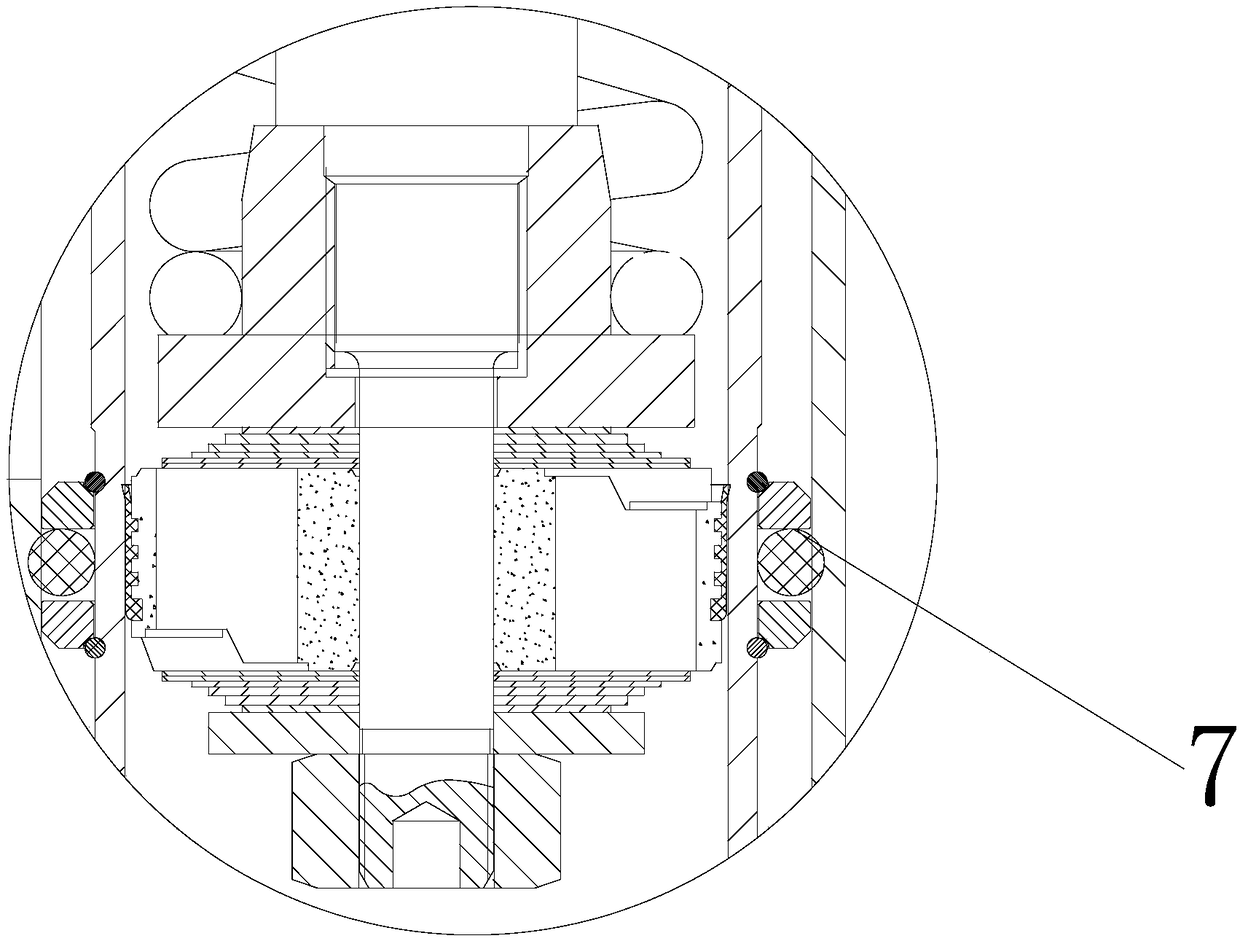
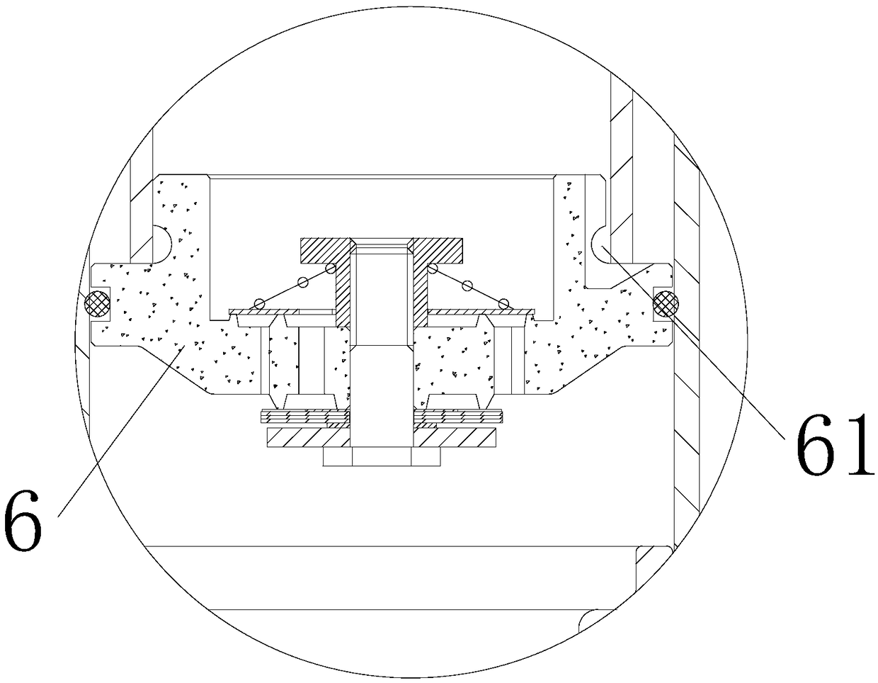
[0028] Such as Figure 1 to Figure 8As shown, the variable damping shock absorber of the present invention includes a liquid storage cylinder 1, and a working cylinder 2 is arranged in the liquid storage cylinder 1, and a piston assembly 3 that can slide relative thereto is arranged in the working cylinder 2; the liquid storage cylinder 1 The upper end of the cylinder is provided with an oil seal guide assembly 4, and the lower end is sealed by the end cover 5; the upper end of the working cylinder 2 is offset against the rubber buffer block 10 arranged inside the oil seal guide assembly 4, and the lower end is arranged against the compression damping block arranged in the liquid storage cylinder 1. The valve 6 offsets; the compression damping valve 6 is provided with a compression damping valve gap 61 communicating with the liquid storage cylinder 1 and the working cy...


PUM


Abstract

The invention provides a variable damping shock absorber. The variable damping shock absorber comprises a liquid storage tube. A working cylinder is arranged in the liquid storage tube. A piston assembly composed of sliding relative to the working cylinder is arranged in the working cylinder. An oil seal guide assembly is arranged at the upper end of the liquid storage tube, and the lower end of the liquid storage tube is sealed through an end cover. The upper end of the working cylinder abuts against the oil seal guide assembly. The lower end of the working cylinder abuts against a compression damper valve arranged in the liquid storage tube. The compression damper valve is provided with a compression damping valve notch. The upper portion of the working cylinder is provided with liquid flow holes A. The two sides of the piston are provided with piston valve throttling damping fin sets. The working cylinder is sleeved with a seal ring assembly. The seal ring assembly divides the liquid storage tube into an upper tube and a lower tube. A solenoid valve is arranged in the liquid storage tube. The variable damping shock absorber has the damping adjustable function, has the good shockabsorption effect and can achieve both comfort and operation stability.

Description

technical field [0001] The invention relates to the technical field of shock absorbers, in particular to variable damping shock absorbers. Background technique [0002] With the development of economy and science and technology, automobiles have become the most important means of transportation for people to travel. In the use of automobiles, its safety and comfort are very important issues. Shock absorbers are a key factor in ensuring the safety and comfort of a car. Traditional shock absorbers cannot reasonably adjust the damping size according to specific road conditions, and cannot switch between comfort performance and handling performance. [0003] The shock absorber with variable damping, as the name suggests, is a shock absorber that can adjust the damping force. When the shock absorber with variable damping is working, the damping force can be adjusted by adjusting the opening of the solenoid valve. For example, Chinese invention patent CN 107869545 A discloses ...

Claims


Application Information

Patent Timeline
Patent Type & Authority Applications(China)
IPC IPC(8): F16F9/34F16F9/512F16F9/32
CPCF16F9/34F16F9/3214F16F9/5123
Inventor 邓鹄孙林桥蒋木林何洪波
Owner XGM CORP LTD
Why Eureka
Try Eureka