Inner pull rod design

An inner tie rod and tie rod technology, applied in the direction of piston rods, mechanical equipment, engine components, etc., can solve the problems of reduced service life of tie rods and pistons, failure to meet normal use requirements, and failure of cylinders to work normally, so as to avoid eccentric wear. , Improve service life and unreliability, reduce friction

Inactive Publication Date: 2018-11-06
联创企业顾问(连云港)有限公司
View PDF6 Cites 1 Cited by
  • Summary
  • Abstract
  • Description
  • Claims
  • Application Information

AI Technical Summary

Problems solved by technology

Here, what we want to talk about is a kind of inner tie rod design; the traditional cylinder has certain disadvantages when it is used. It causes the service life of the tie rod and the piston to be reduced, and when it shrinks back and forth, it is easy to generate vibration and affect the stable operation of the equipment. It will also cause friction to cause serious wear on the surface of the tie rod, which cannot meet people's normal use requirements, and brings certain problems to the use of the cylinder. Trouble, for this we propose an inner tie rod design

Method used


Image

  • Inner pull rod design
  • Inner pull rod design
  • Inner pull rod design

Examples


Embodiment 1

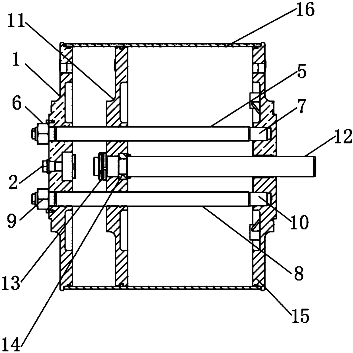
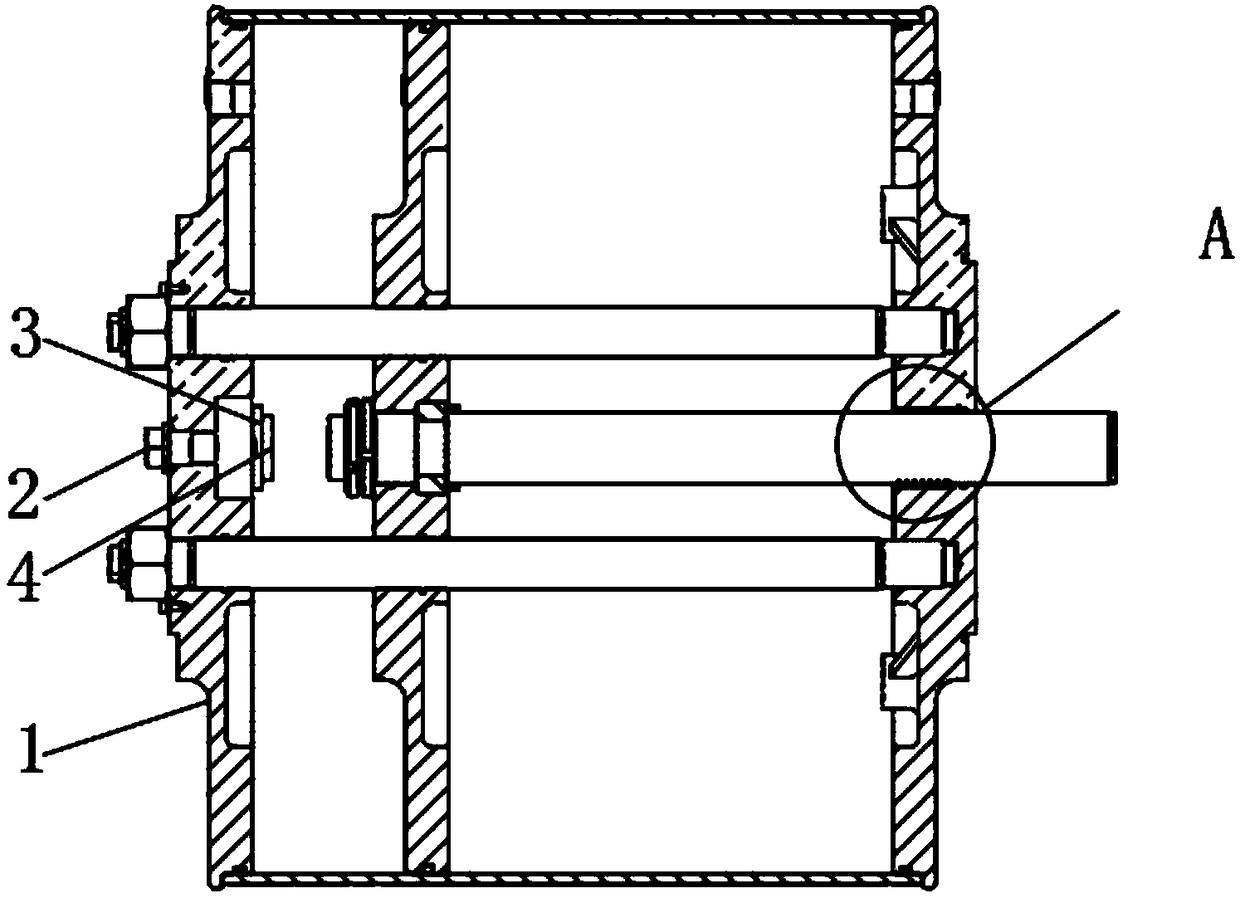
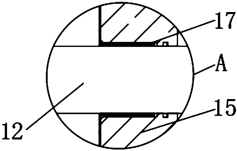
[0019] Such as Figure 1-3 As shown, a design of an inner tie rod includes a No. 1 cylinder head 1 and a No. 2 cylinder head 15. A fastening bolt 2 is movably installed on the inner surface of one end of the No. 1 cylinder head 1 near the middle, and the other side of the fastening bolt 2 A fixing seat 3 is fixedly installed on the outer surface of one end, and a cushion block 4 is provided on one side of the outer surface of the fixing seat 3, and a No. 1 pull rod 5 is provided on the inner surface of one end of the No. 1 cylinder head 1 above the fastening bolt 2. No. 1 nut 6 is movably installed on the outer surface of No. 1 pull rod 5, and No. 1 connector 7 is fixedly installed on the outer surface of one end of No. 1 pull rod 5. There is No. 2 tie rod 8, No. 2 nut 9 is movably installed on the outer surface of No. 2 tie rod 8, and No. 2 connector 10 is fixedly installed on the outer surface of one end of No. 2 tie rod 8. One side of No. 1 cylinder head 1 is provided with ...


PUM


Abstract

The invention discloses an inner pull rod design. The inner pull rod design comprises a first cylinder head and a second cylinder head. A fastening bolt is movably mounted at the position, near the middle, of the inner surface of one end of the first cylinder head, and a fixing seat is fixedly mounted on the outer surface of the other end of the fastening bolt. A buffer cushion block is arranged on the outer surface of one side of the fixing seat, and a first pull rod is arranged at the position, located above the fastening bolt, of the inner surface of one end of the first cylinder head. A first nut is movably mounted on the outer surface of the first pull rod, and a first connector is fixedly mounted on the outer surface of one end of the first pull rod. The inner pull rod design is provided with the buffer cushion block, the first pull rod, a second pull rod and rolling steel balls, vibration generated when the pull rods are in telescopic contact can be reduced, and the service lifeof an air cylinder can be prolonged and the unreliability of the air cylinder can be improved, the friction generated by the pull rods during moving can be further reduced, and the inner pull rod design is suitable for different working conditions and brings better use prospects.

Description

technical field [0001] The invention relates to the field of mechanical equipment, in particular to a design of an inner tie rod. Background technique [0002] Cylinder, a cylindrical metal part that guides the piston to perform linear reciprocating motion in the cylinder. Air expands in the engine cylinders to convert thermal energy into mechanical energy; gas is compressed by pistons in the compressor cylinders to increase its pressure. Here, what we want to talk about is a kind of inner tie rod design; the traditional cylinder has certain disadvantages when it is used. It causes the service life of the tie rod and the piston to be reduced, and when it shrinks back and forth, it is easy to generate vibration and affect the stable operation of the equipment. It will also cause friction to cause serious wear on the surface of the tie rod, which cannot meet people's normal use requirements, and brings certain problems to the use of the cylinder. Trouble, for this we came up...

Claims


Application Information

Patent Timeline
Patent Type & Authority Applications(China)
IPC IPC(8): F16F15/04F16J7/00F16J10/02F16J1/00
CPCF16F15/04F16J1/00F16J7/00F16J10/02
Inventor 张岩
Owner 联创企业顾问(连云港)有限公司
Why Eureka
Try Eureka