Independent compact type expansion joint with inlet and outlet perpendicular to each other

An independent and compact technology, applied in the field of expansion joints, can solve the problems of inability to adapt to different places of use, poor construction flexibility, troublesome installation and disassembly, etc., to achieve easy maintenance or replacement, improve adaptability, and easy installation and disassembly Effect

Active Publication Date: 2018-11-06
江苏乾元飞达电力设备有限公司
View PDF6 Cites 0 Cited by
  • Summary
  • Abstract
  • Description
  • Claims
  • Application Information

AI Technical Summary

Problems solved by technology

[0002] In the prior art: the patent application publication number CN 207195934 U discloses a vertical independent compact expansion joint with an inlet and outlet. The inlet pipe, bellows, elbow and outlet pipe are connected sequentially. The tubes are perpendicular to each other. There are two vertical plates on the outer tube wall of the inlet end tube. Two long rods are connected between the two vertical plates. The long rods extend toward the direction of the bend. There is a cylindrical support body on the board, the bottom of the cylindrical support body is sealed and the top opening is on the support horizontal plate. There is a spring in the cylindrical support body. The spring is connected to the elbow through a support rod. The outer surface of the elbow pipe is welded with a support The vertical plate and the supporting horizontal plate are provided with a spring support, and the bottom of the support vertical plate is connected with the spring support. It is troublesome to install and disassemble, inconvenient to maintain, and its construction flexibility is poor, so it cannot be adapted to different places of use.

Method used


Image

  • Independent compact type expansion joint with inlet and outlet perpendicular to each other

Examples


Embodiment Construction

[0020] The following will clearly and completely describe the technical solutions in the embodiments of the present invention with reference to the accompanying drawings in the embodiments of the present invention. Obviously, the described embodiments are only some, not all, embodiments of the present invention. Based on the embodiments of the present invention, all other embodiments obtained by persons of ordinary skill in the art without making creative efforts belong to the protection scope of the present invention.

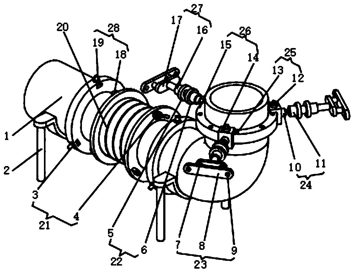
[0021] see figure 1 , the present invention provides a technical solution: an independent compact expansion joint with a vertical inlet and outlet, including a delivery pipe 1, the delivery pipe 1 is an L-shaped structure, the inlet end and the outlet end of the delivery pipe 1 are perpendicular to each other, and the delivery pipe 1 The support frame 2 is fixed at the bottom of the transverse tube, and the transverse tube of the conveying pipe 1 is clamped wi...


PUM


Abstract

The invention discloses an independent compact type expansion joint with an inlet and an outlet perpendicular to each other. The independent compact type expansion joint comprises a conveying pipe ofan L-shaped structure; the inlet end and the outlet end of the conveying pipe are perpendicular to each other; and a supporting frame is fixedly arranged at the bottom of a transverse pipe of the conveying pipe. According to the independent compact type expansion joint with the inlet and the outlet perpendicular to each other, a fabric compensator and the conveying pipe are mounted by clamping a first fastener and a locating groove, so that the independent compact type expansion joint is convenient to mount and dismount, and the fabric compensator is convenient to maintain or replace; the fabric compensator is mainly made of high-temperature resistant materials such as fiber fabric and rubber, and can compensate axial-, transverse- and angular-direction products and so on; the independentcompact type expansion joint has the characteristics of no push force, simplicity in support design, corrosion resistance, high temperature resistance, noise elimination, damping, etc.; and the fabriccompensator and the conveying pipe are fixed by plugging a first locker and a first lock hole, so that the fabric compensator is prevented from loosening during operating, and the safety of the expansion joint in use is ensured.

Description

technical field [0001] The invention relates to the technical field of expansion joints, in particular to an independent compact expansion joint with a vertical inlet and outlet. Background technique [0002] In the prior art: the patent application publication number CN 207195934 U discloses a vertical independent compact expansion joint with an inlet and outlet. The inlet pipe, bellows, elbow and outlet pipe are connected sequentially. The tubes are perpendicular to each other. There are two vertical plates on the outer tube wall of the inlet end tube. Two long rods are connected between the two vertical plates. The long rods extend toward the direction of the bend. There is a cylindrical support body on the board, the bottom of the cylindrical support body is sealed and the top opening is on the support horizontal plate. There is a spring in the cylindrical support body. The spring is connected to the elbow through a support rod. The outer surface of the elbow pipe is wel...

Claims


Application Information

Patent Timeline
Patent Type & Authority Applications(China)
IPC IPC(8): F16L51/02F16L3/16
CPCF16L3/16F16L51/024
Inventor 仇为名
Owner 江苏乾元飞达电力设备有限公司
Why Eureka
Try Eureka