
Drum type cotton drying equipment

A drying equipment and a drum-type technology, applied in the field of drum-type cotton drying equipment, can solve the problems of poor drying quality of cotton balls that cannot meet standards, uneven drying and blowing of cotton balls, blocking drying wind circulation, etc. The effect of reducing the difficulty of loading and unloading operations, good butt sealing, and convenient operation

Pending Publication Date: 2018-11-06
向世豪
View PDF7 Cites 5 Cited by
  • Summary
  • Abstract
  • Description
  • Claims
  • Application Information

AI Technical Summary

Problems solved by technology

[0007] In order to solve the above-mentioned technical problems, the present invention provides a drum-type cotton drying equipment to solve the problem that the existing cotton drying equipment usually uses hot air to blow vertically upward or in parallel for drying, and the drying rack inside the equipment is equipped with With multiple layers, these drying racks will block the circulation of the drying air and affect its penetration, which will cause the cotton balls on the upper or inner drying racks to not be fully and evenly dried and blown, resulting in poor drying quality of the cotton balls. Problems that are poor and cannot meet the standard

Method used


Image

  • Drum type cotton drying equipment
  • Drum type cotton drying equipment
  • Drum type cotton drying equipment

Examples


Embodiment

[0044] as attached figure 1 to attach Figure 13 Shown:

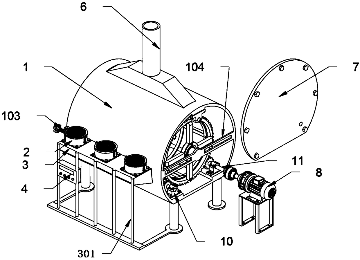
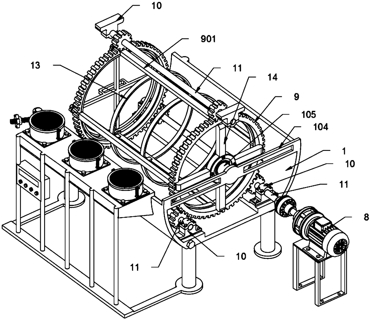
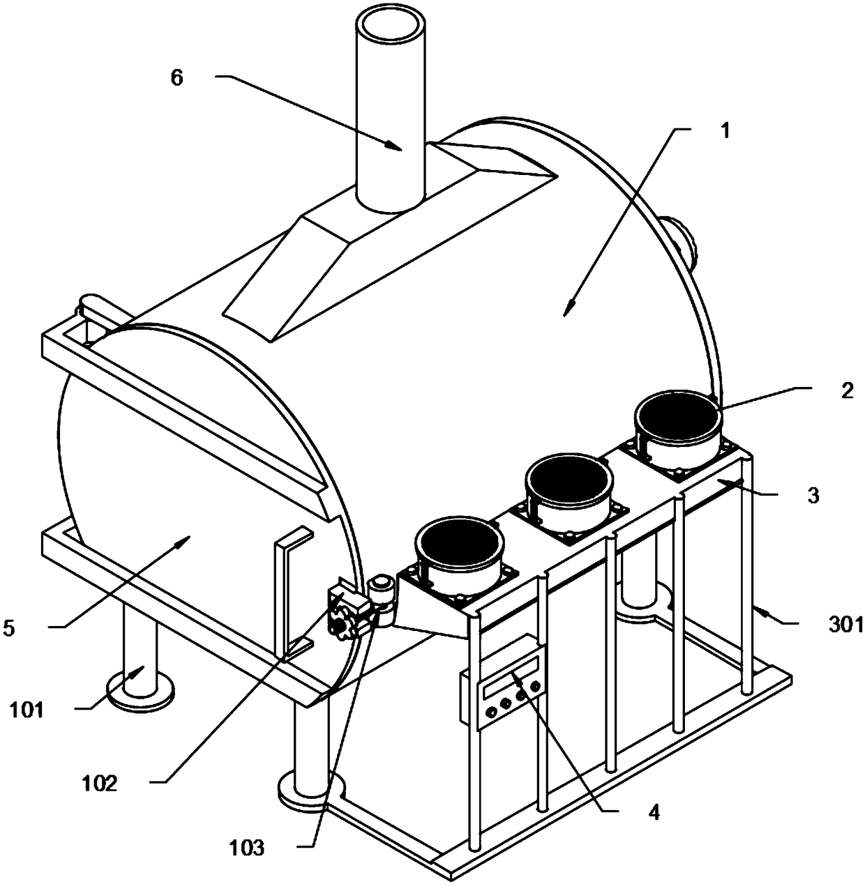
[0045] The invention provides a drum-type cotton drying equipment, which includes a drying box 1, a support leg 101, a buckle plate 102, a locking bolt 103, a positioning frame 104, a positioning shaft 105, an electric heating fan 2, a fan filter 201, a pull Tight spring 202, bellows 3, bellows support rod 301, control electric box 4, box door 5, air outlet pipe 6, drying box rear baffle 7, drive motor 8, rolling frame 9, support chute 901, bearing seat 10 , a rotating shaft 11, a gear 111, a bucket cover 12, a cotton bucket 13 and a fixed frame 14, the whole of the drying box 1 is arranged in a cylindrical bottom plane cut, and a box door 5 is hinged in its front rotation, and its rear end There is a box rear baffle 7 for screw locking and sealing; the bottom of the flat bottom plate of the drying box 1 is symmetrically supported by four supporting legs 101; Pipe 6, and a bellows 3 is welded and connected on the out...


PUM


Abstract

The invention discloses a drum type cotton drying equipment. The equipment comprises a gear, a barrel cover, a cotton barrel and a fixing frame, wherein the barrel cover is formed by both combining supporting rings on the outside and cross-shaped supporting frames which are connected inside the supporting rings in a supporting mode, and the cross-shaped supporting frames divides the supporting rings into four parts at interval, and a layer of metal net is connected with the interiors of space-gap fan-shaped grooves with four equal-size parts in a covering mode correspondingly; and the fixing frame is welded on the end face, of the outer end of a rotating ring, at the rear end of a rolling frame in a supporting mode, the fixing frame is formed by jointly supporting of the central bearing sleeve and four supporting rods which are welded on the central bearing sleeve in a cross-shaped mode, moreover, a bearing is embedded inside the central bearing sleeve, and the bearing is tightly pressed and positioned through two bearing covers which are in threaded tight locking at the front end and the rear end of the central bearing sleeve. According to the equipment, three sets of gears are arranged, the three sets of gears on the three rotating shafts can be used for carrying out meshing positioning on the rolling frame, so that the rolling frame can be stably rotated among the three setsof gears to carry out rotary drying operation.

Description

technical field [0001] The invention belongs to the technical field of cotton drying machinery, and more specifically relates to a drum type cotton drying equipment. Background technique [0002] The newly picked seed cotton has high humidity, usually between 15 and 22. In order to prevent the cotton from mildew during transportation and storage, it is necessary to dry the cotton in time to reduce the moisture content of the cotton to below 8%. , because natural drying is affected by weather conditions, a large site is required, and the efficiency of drying is low, therefore, it cannot meet the needs of large-scale cotton production, which requires a cotton drying equipment to solve the above problems [0003] After searching, for example, the patent No. CN206891066U discloses a drying device for cotton processing, which includes an electric heating box, and three vibrating plates are arranged in sequence from top to bottom inside the electric heating box, and the side of ea...

Claims


Application Information

Patent Timeline
Patent Type & Authority Applications(China)
IPC IPC(8): F26B11/04F26B21/10F26B25/16
CPCF26B11/04F26B21/10F26B25/16
Inventor 楼天培
Owner 向世豪
Learn More