AI technical title is built by PatSnap AI team. It summarizes the technical point description of the patent document.
A cooling tower and energy technology, applied in the field of industrial cooling towers, can solve the problems of space limitation, high exhaust gas temperature, freezing, etc., and achieve the effect of prolonging the contact path and time, increasing the contact area, and rationally utilizing energy
Active Publication Date: 2019-11-22
黑龙江陆地能源有限公司
View PDF7 Cites 0 Cited by
Summary
Abstract
Description
Claims
Application Information
AI Technical Summary
This helps you quickly interpret patents by identifying the three key elements:
Problems solved by technology
Method used
Benefits of technology
Problems solved by technology
[0003] In view of the space limitation of the cooling tower water eliminator in the prior art, the exhaust gas temperature is high, the moisture content is large, the water collection effect is not good, the water mist at the exhaust port is serious, the conventional heat storage device is inefficient, and the steam cannot be fully utilized The problem of icing when the heat is out of service or when the temperature is low, the invention provides an energy allocation device for cooling towers
Method used
Image
Click on the blue label to locate the original text in one second.
Reading with bidirectional positioning of images and text.
Examples
Embodiment Construction
[0025] The technical solutions in the embodiments of the present invention will be clearly and completely described below in conjunction with the accompanying drawings in the embodiments of the present invention. Obviously, the described embodiments are only part of the embodiments of the present invention, not all of them. . Based on the embodiments of the present invention, all other embodiments obtained by persons of ordinary skill in the art without making creative efforts belong to the protection scope of the present invention.
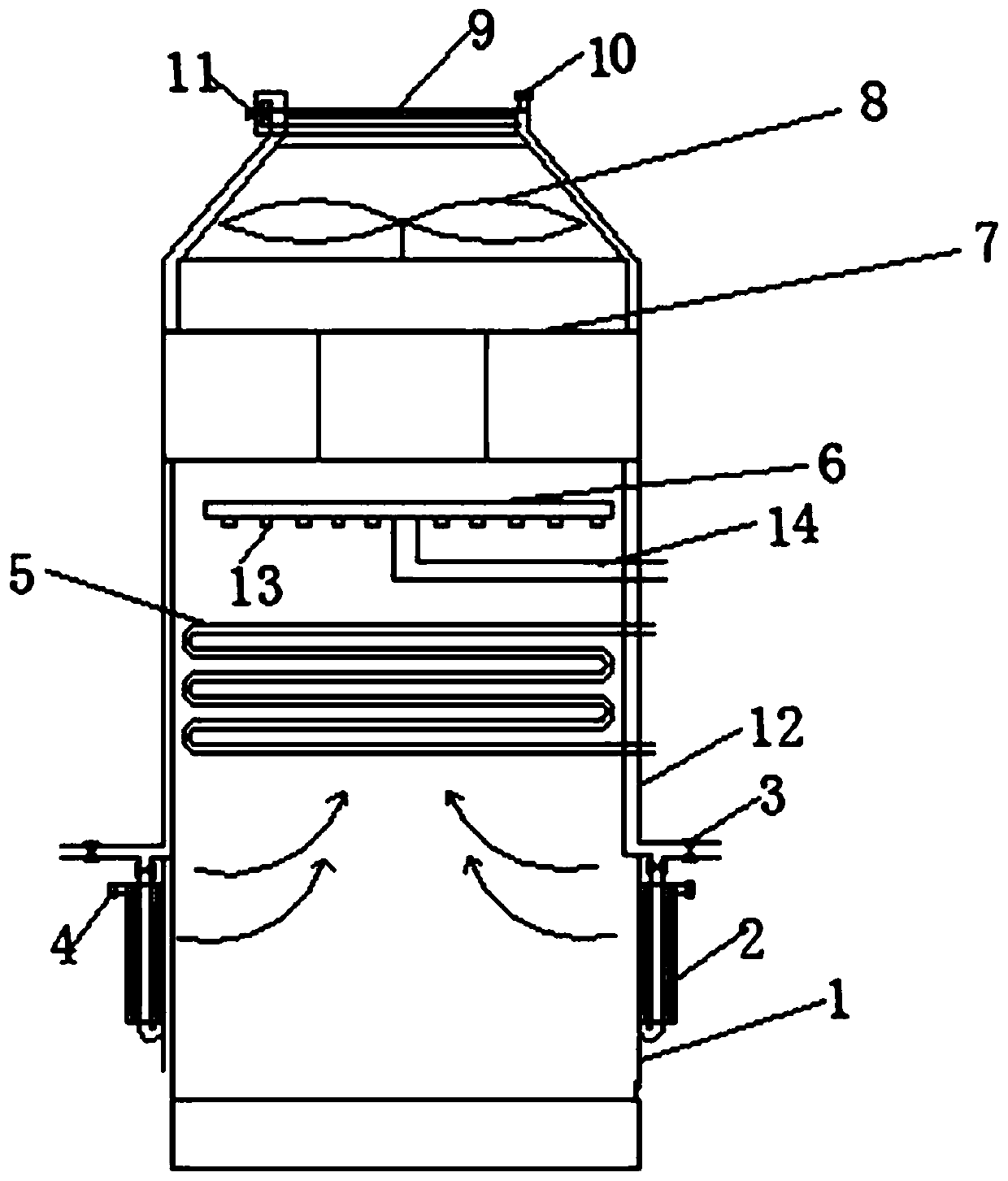
[0026] Such as figure 1 As shown, the air inlet is arranged on the left and right sides of the lower end of the cooling tower body 1, and the air guide vane 2 is wound and installed on the air inlet. The cold wind passes through the air inlet and enters the cooling tower 1 under the guidance of the air guide vane 2. The bracket is arranged on the top of the cooling tower 1, the lower end of the top cover, through the rotation of the rotating fan...
PUM
Abstract
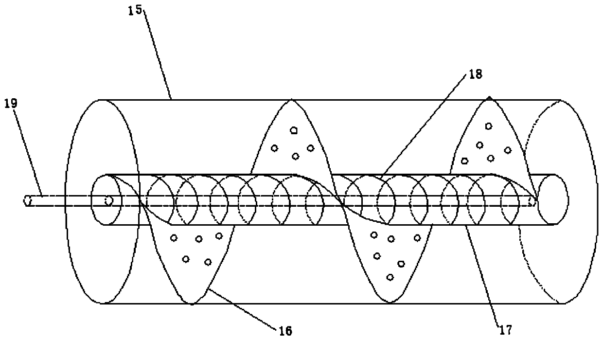
The invention relates to a cooling tower energy utilization device comprising a cooling tower body, an air inlet, a wind guide vane, valves I-IV, temperature sensors I-II, a hot water pipe, a water spray pipe, a water inlet pipe, nozzles, a heat storage device, a rotating fan blade, a valve V, a cooling tower top cover, a temperature sensor III and a surrounding heat source tube; through the arrangement of a spiral heat storage plate, a heat storage chamber, a spiral groove, a heat conducting pipe, and a diaphragm cavity in the heat storage device, heat carried by hot air after heat exchange is stored and released, the part of the wasted heat is recovered, the problem of icing of an inlet position and an outlet position in the case of low environment temperature, shutdown and the like canbe solved, no additional heat source or no additional introduction of a mixed gas is needed, resources are saved, energy is rationally used, and waste is reduced.
Description
technical field [0001] The invention relates to the field of industrial cooling towers, in particular to an energy allocation device for cooling towers. Background technique [0002] The cooling tower is a conventional industrial heat exchange device. The air enters the tower body through the air inlet, and forms a countercurrent heat exchange with the water sprayed by the spray device. The liquid water evaporates and absorbs heat, takes away the heat of the heat source, and becomes high-temperature steam. Continue to rise, after passing through the water eliminator, a part of the liquid droplets will condense, and the remaining gas will continue to be discharged upwards from the air outlet. In winter or when the operation is out of service and the ambient temperature is low at night, at the air inlet and outlet of the cooling tower, Icing often occurs. At the same time, due to the large water vapor at the position of the air outlet, and the low ambient temperature, there is...
Claims
Application Information
Patent Timeline
Application Date:The date an application was filed.
Publication Date:The date a patent or application was officially published.
First Publication Date:The earliest publication date of a patent with the same application number.
Issue Date:Publication date of the patent grant document.
PCT Entry Date:The Entry date of PCT National Phase.
Estimated Expiry Date:The statutory expiry date of a patent right according to the Patent Law, and it is the longest term of protection that the patent right can achieve without the termination of the patent right due to other reasons(Term extension factor has been taken into account ).
Invalid Date:Actual expiry date is based on effective date or publication date of legal transaction data of invalid patent.

