A method and device for measuring ultrashort laser pulse width

A pulse width, ultra-short laser technology, applied in the direction of instruments, etc., can solve problems such as cumbersome operation, complex structure, and impact

Active Publication Date: 2020-01-17
XIAMEN UNIV
View PDF14 Cites 1 Cited by
  • Summary
  • Abstract
  • Description
  • Claims
  • Application Information

AI Technical Summary

Problems solved by technology

Their overall idea is to divide the laser into two beams of light, add an adjustable mechanical stepper motor to the optical path of one of the beams, and then converge the two beams of light on the nonlinear crystal, and realize the laser by controlling the stepper motor and using phase matching. For the measurement of pulse width, the method not only requires nonlinear crystals (for optical frequency doubling, sum frequency, etc.), but also has a complex structure (not all-fiber structure), is expensive, and is basically monopolized by foreign companies (such as APE in Germany, Femtochrome in the United States, etc.) Research, etc.)
In addition, the above-mentioned technologies all have the problem of cumbersome operation (requires multi-component linkage and precise adjustment), making it difficult to use; and the measurement laser band is limited, and the nonlinear optical frequency-doubling crystal needs to be replaced frequently for different laser bands. The effect of polarization state is obvious
[0004] The early two-photon fluorescence method and streak camera can also measure picosecond laser pulse width, but the former has a strong background interference signal, making it difficult to detect the weak signal near the main pulse, and the latter is expensive and time-consuming. Latency and dynamic range are not easy to adjust, and the time resolution is low (a few picoseconds)

Method used


Image

  • A method and device for measuring ultrashort laser pulse width
  • A method and device for measuring ultrashort laser pulse width
  • A method and device for measuring ultrashort laser pulse width

Examples


Embodiment 1

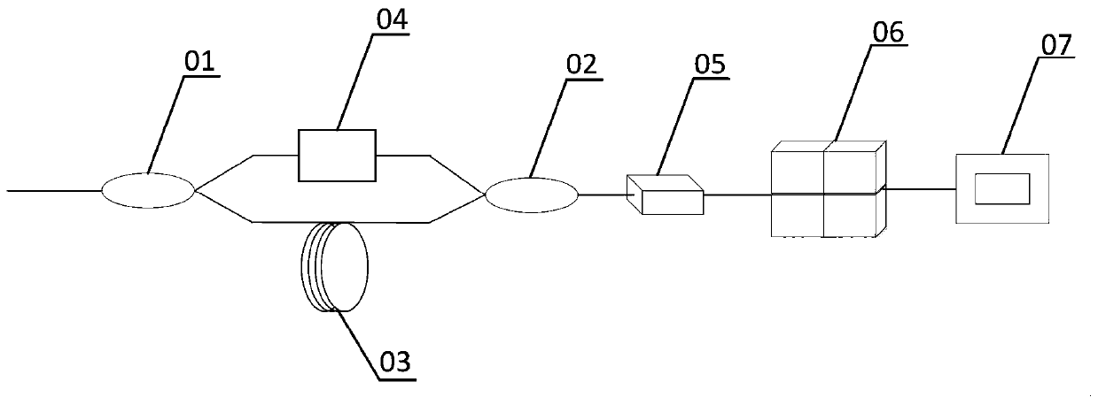
[0028] refer to figure 1 , this example provides a measuring device for ultrashort laser pulse width, including a first fiber coupler 1, a second fiber coupler 2, an optical path difference matching fiber 3, an optical fiber adjustable delay device 4, a photodetector 5, a data Acquisition card 6, data processing system 7. Wherein the common input end of the first optical fiber coupler 1 is connected to the pulsed laser to be measured, and the function of the first optical fiber coupler is to divide the input pulsed laser into two beams equally; one of its two output ends is connected to the boom, i.e. The input end of the optical fiber adjustable delay device 4, the other end is connected to the reference arm, and the input end of a section of optical path difference matching optical fiber 3 is connected to the reference arm, which is used to accurately match the optical path of the two arms and optimize the coherence characteristics of the two paths; the optical fiber The ou...

Embodiment 2

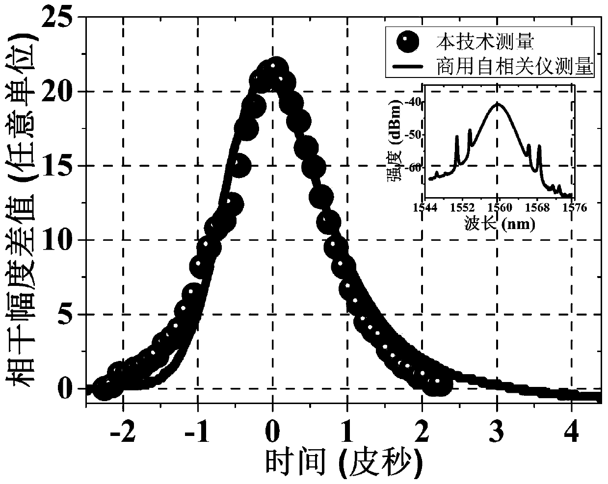
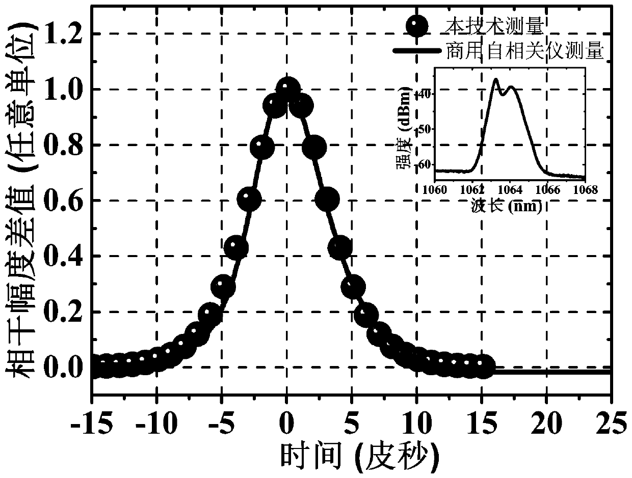
[0031] Using the device of Example 1 to measure the pulse width of the mode-locked laser whose pulse width is unknown at 1.56 μm, specifically includes the following steps:

[0032] 1. Open the power supply of optical fiber adjustable delay device 4, photodetector 5 and data processing system 7 respectively; Connect the data connecting line of optical fiber adjustable delay device 4 and data acquisition card 6 with data processing system 7;

[0033]2. Synchronously trigger the delay time point of the optical fiber delay device 4 and the acquisition time point of the data acquisition card 6 through the data processing system 7, adjust the delay amount within the maximum delay time range of the fiber delay device 4, and adjust the delay amount within the maximum delay time range of the optical fiber delay device 4. In the section, calculate the maximum interference amplitude fluctuation difference of the two laser pulses at each delay time point one by one due to interference; in...


PUM


Abstract

The invention provides an ultra-short laser pulse width measurement method and device. Laser pulse to be measured is divided into two paths, and one path adjusts delay time to make overlapped interference with the other path of laser pulse. Fluctuation of the intensity coherent amplitude of the laser pulse is collected in each delayed time point, and a data processing system obtains the maximum and minimum of the amplitude, calculates a difference therebetween. The interference overlap areas of two paths of laser pulses are different in different delayed time points, the differences of pulse interference amplitude fluctuation are different, amplitude fluctuation differences in one to one correspondence to the delayed time are obtained, namely, a time-domain shaped curve of the ultra-shortlaser pulse is obtained, and further the pulse width is obtained. According to the method and device, the structure is simple, the cost is low, the method and device tend not to be interfered by the outside, enclosed measurement can be realized, operation is simple, the wavelength and pulse width measuring range is wide, the precision is high, the size is small and the device is also portable.

Description

technical field [0001] The invention relates to a new method for measuring laser pulse width, in particular to a method and device for measuring ultrashort pulse width. Background technique [0002] Ultrashort pulse laser has important application value in chemical molecular identification, biomedicine, physics, laser precision processing and other fields. It can generate high peak power at low power consumption and has become an important production tool. Whether it is scientific research or industrial application, the pulse width information of ultrashort lasers must be accurately known in order to fully understand and use such lasers; that is, pulse width measurement or the fine structure of spectroscopic pulses (picosecond or femtosecond pulses) are the key to manufacture and use. The key to ultrashort pulse lasers. At present, with the advancement of oscilloscope technology, laser pulse widths of milliseconds, microseconds, nanoseconds or even hundreds of picoseconds c...

Claims


Application Information

Patent Timeline
Patent Type & Authority Patents(China)
IPC IPC(8): G01J11/00
CPCG01J11/00
Inventor 罗正钱杨润华王鸿健
Owner XIAMEN UNIV
Why Eureka
Try Eureka