A Power Factor Correction Control System

A power factor correction and control system technology, applied in the direction of output power conversion devices, climate sustainability, high-efficiency power electronic conversion, etc., can solve the problems of uncontrollable systems and incomplete sliding processes, etc., to eliminate unpredictable, The effect of eliminating system changes and ensuring stability

Active Publication Date: 2019-05-24
HUAIYIN INSTITUTE OF TECHNOLOGY
View PDF0 Cites 0 Cited by
  • Summary
  • Abstract
  • Description
  • Claims
  • Application Information

AI Technical Summary

Problems solved by technology

[0005] The technical problem to be solved by the present invention is to provide a power factor correction control system, which can solve the problem that the traditional sliding mode control (SMC) may not be able to complete the sliding process when there is interference in the system, which may lead to the problem that the system cannot be controlled

Method used


Image

  • A Power Factor Correction Control System
  • A Power Factor Correction Control System
  • A Power Factor Correction Control System

Examples


Embodiment Construction

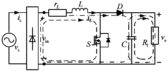
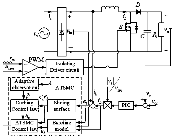
[0061] Such as figure 2 A power factor correction control system is shown, including such as figure 1 A boost type power factor correction (PFC) circuit and a control unit are shown, and the control unit performs the following steps:

[0062] 1) Use the nominal value and variation to represent the component parameters of the power factor correction circuit, the grid voltage v in the step-up PFC circuit s =V s sin ωt, i s is the grid current, the output v of the rectifier bridge is not controlled in =|V s sinωt|, |g| is the absolute value operator, L is the input inductance, r L is the equivalent resistance of the inductor, S is the main switch, D is the output diode, C is the output capacitor, R l is the load resistance, i L and v o are the inductor current and the DC output voltage, respectively.

[0063] When S is turned on, the inductor L is in the energy storage stage, and the capacitor C is the load R l To provide energy, the current path as figure 1 As shown ...


PUM


Abstract

The invention discloses a power factor correction control system. The system comprises a power factor correction circuit and a control unit; the control unit executes the following steps: 1) representing an element parameter of the power factor correction circuit by adopting a nominal value and variable quantity, and establishing a current state spatial model of the power factor correction circuit; 2) operating a total-field sliding mode control TSMC algorithm, wherein the algorithm comprises two parts: acquiring expected performance according to a reference model and designing a constraint controller. The element parameter is represented by using the nominal value and the variable quantity so as to establish the current state spatial model, thereby improving the robustness on the parameter change by the controller. On the one hand, the TSMC algorithm can acquire the expected performance according to a nominal model, and on the other hand, the tracking error of the inductor current canbe always maintained on the sliding mode surface by designing the constraint controller, and the tracking error of the inductor current gradually tends to zero.

Description

technical field [0001] The invention relates to the technical field of power factor correction, in particular to a power factor correction control system. Background technique [0002] At present, the common electric vehicle charging device uses an uncontrolled rectifier bridge for rectification. During the process of the rectifier bridge converting the AC power of the grid into DC power that can be used by the battery of the electric vehicle, the grid-side current contains a large number of multiple harmonics, resulting in distortion of the grid voltage. , will have adverse effects on the components and loads in the main circuit. Power factor correction (PFC) can make the grid-side input current waveform track the grid voltage waveform, and correct it to a sine wave with the same phase as the input voltage, improve the power factor, greatly reduce voltage and current harmonics, and obtain smooth and stable output at the same time DC voltage, and improve circuit transmissio...

Claims


Application Information

Patent Timeline
Patent Type & Authority Patents(China)
IPC IPC(8): H02M1/42
CPCH02M1/4225Y02B70/10
Inventor 王业琴杨艳陈语嫣夏奥运郭畅刘璐王星月陈万
Owner HUAIYIN INSTITUTE OF TECHNOLOGY
Why Eureka
Try Eureka