
Differential line winding method

A winding method and differential line technology, applied in printed circuit components, electrical components, printed circuits, etc., can solve the problem of large PCB space and achieve the effect of reducing PCB space

Inactive Publication Date: 2018-11-06
HEFEI LCFC INFORMATION TECH
View PDF11 Cites 1 Cited by
  • Summary
  • Abstract
  • Description
  • Claims
  • Application Information

AI Technical Summary

Problems solved by technology

[0006] This application provides a differential line winding method; to solve the problem that the 3w2s winding rule occupies a large PCB space

Method used

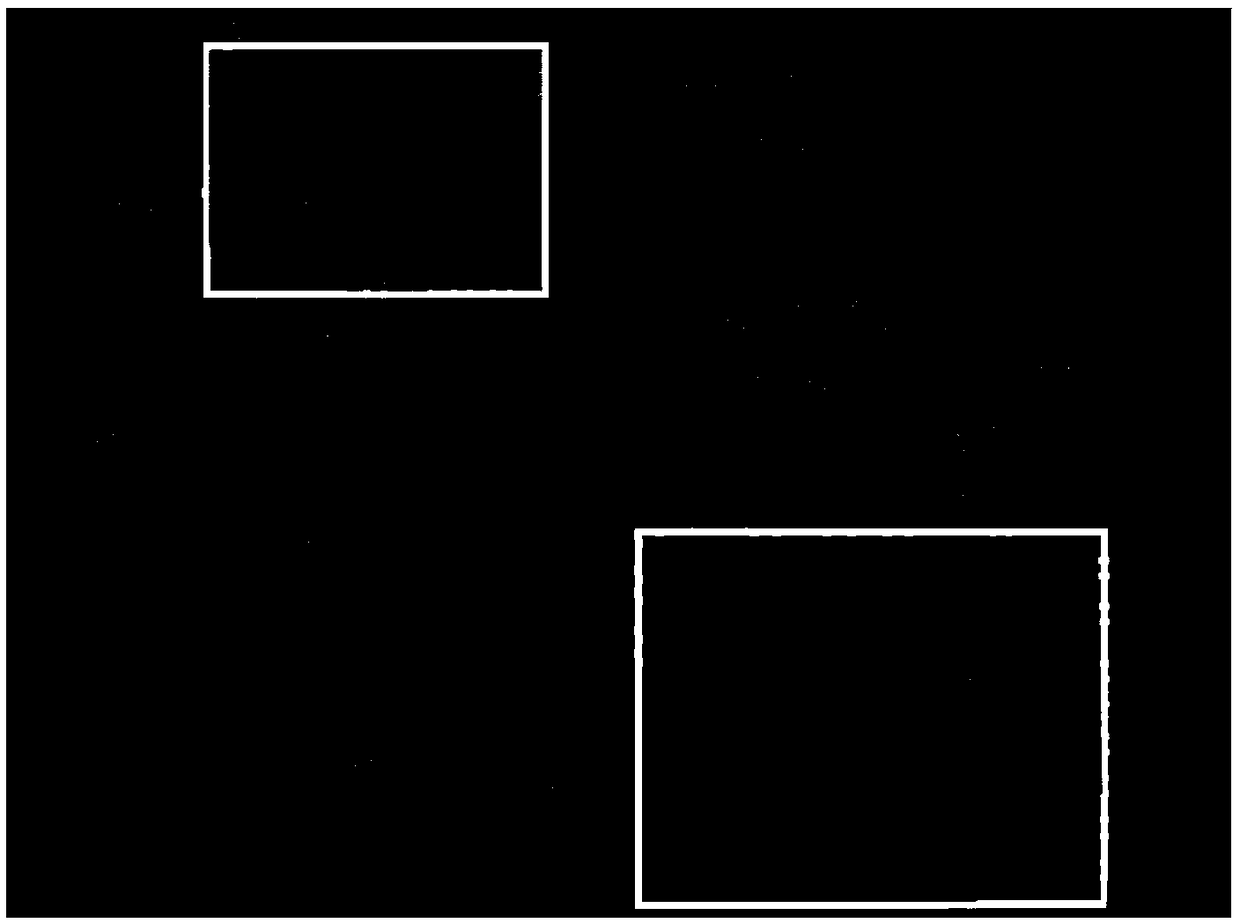
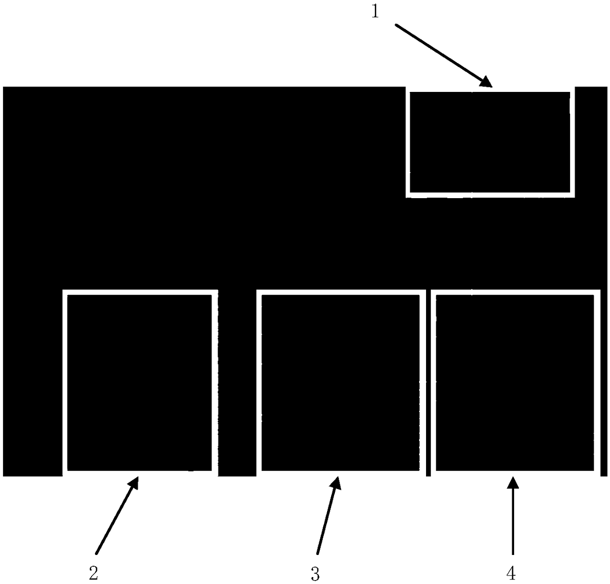
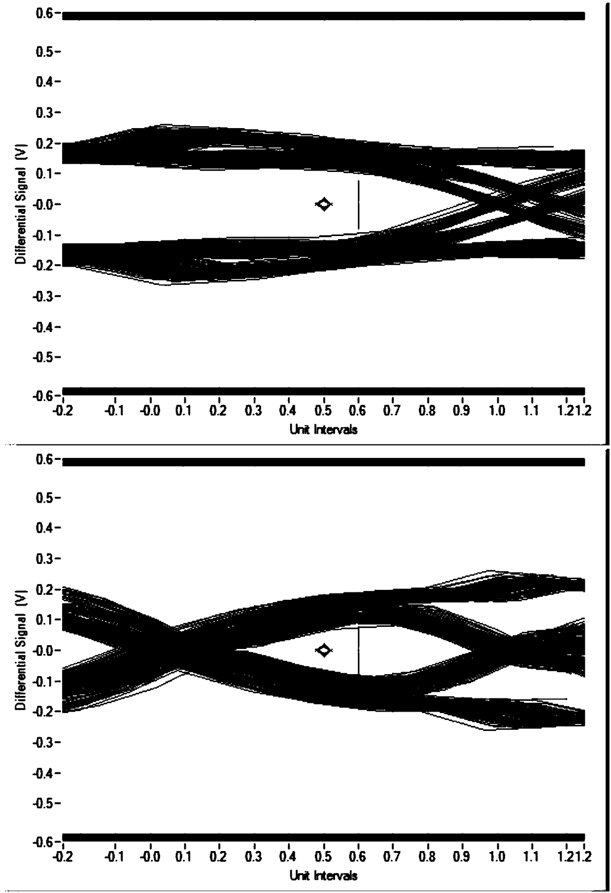

Image

  • Differential line winding method
  • Differential line winding method
  • Differential line winding method

Examples


Embodiment Construction

[0028] Below, specific embodiments of the present application will be described in detail in conjunction with the accompanying drawings, but it is not intended as a limitation of the present application.

[0029] It should be understood that various modifications may be made to the embodiments disclosed herein. Accordingly, the above description should not be viewed as limiting, but only as exemplifications of embodiments. Those skilled in the art will envision other modifications within the scope and spirit of the application.

[0030] The accompanying drawings, which are incorporated in and constitute a part of this specification, illustrate embodiments of the application and, together with the general description of the application given above and the detailed description of the embodiments given below, serve to explain the embodiments of the application. principle.

[0031] These and other characteristics of the present application will become apparent from the following...


PUM


Abstract

The invention provides a differential line winding method. The differential line winding method comprises the following steps: associating a first line of a differential line with a first hole; associating a second line of the differential line with a second hole, and causing the second line to protrude toward a direction away from the first line, so that a differential signal is matched at equallength. The method disclosed by the invention breaks through the limitation of 3W2S, and can solve the equal length matching problem of the differential signal just by using a winding unit combined with a through hole without generating problems in terms of SI of the signal. By adoption of the method, the PCB space needed for equal length winding of the differential high-speed signal on a differential line main circuit can be effectively reduced.

Description

technical field [0001] This application relates to the field of circuit boards, in particular to a differential wire winding method. Background technique [0002] Currently, electronic devices have more and more functions, and the number of electronic components per unit area of ​​a printed circuit board (abbreviated as PCB) is increasing. With the continuous reduction of the motherboard area, the requirements for equal-length matching of high-speed signals are getting higher and higher. [0003] Differential signal, also known as differential signal, means that the driver sends two signals of equal value and opposite phase, and the receiving end judges whether the logic state is "0" or "1" by comparing the difference between the two voltages. [0004] Differential lines are two lines that carry differential signals on the PCB. The differential line transmits exactly the same signal with opposite polarity, and the judgment is made by the signal level difference of the two ...

Claims


Application Information

Patent Timeline
Patent Type & Authority Applications(China)
IPC IPC(8): H05K1/02
CPCH05K1/0245
Inventor 刘艳萍金慧
Owner HEFEI LCFC INFORMATION TECH
Learn More