Improved photoelectric module assembly parts

A technology of photoelectric modules and components, applied in optical components, electrical components, optics, etc., can solve problems such as occupation, multiple PCB space, and inability to provide shielding electromagnetic interference, so as to improve overall capacity, save PCB space, and enhance EMI shielding ability Effect

Inactive Publication Date: 2005-06-01
BROADCOM INT PTE LTD
View PDF0 Cites 0 Cited by
  • Summary
  • Abstract
  • Description
  • Claims
  • Application Information

AI Technical Summary

Problems solved by technology

[0005] Fixing the optical module directly on the board requires too much PCB space, and the figure 1 The chassis assembly shown is such that the module can only be inserted through the front of the board
[0006] Moreover, the above-mentioned mounting methods alone do not provide sufficient shielding against electromagnetic interference (EMI)
EMI shielding function needs to be obtained by additional independent shielding device, thus occupying more PCB space

Method used


Image

  • Improved photoelectric module assembly parts
  • Improved photoelectric module assembly parts
  • Improved photoelectric module assembly parts

Examples


Embodiment Construction

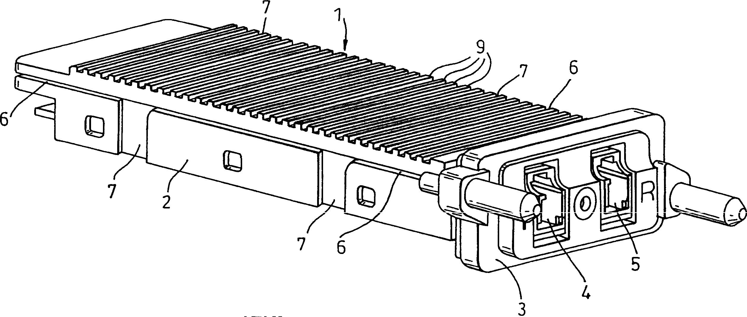
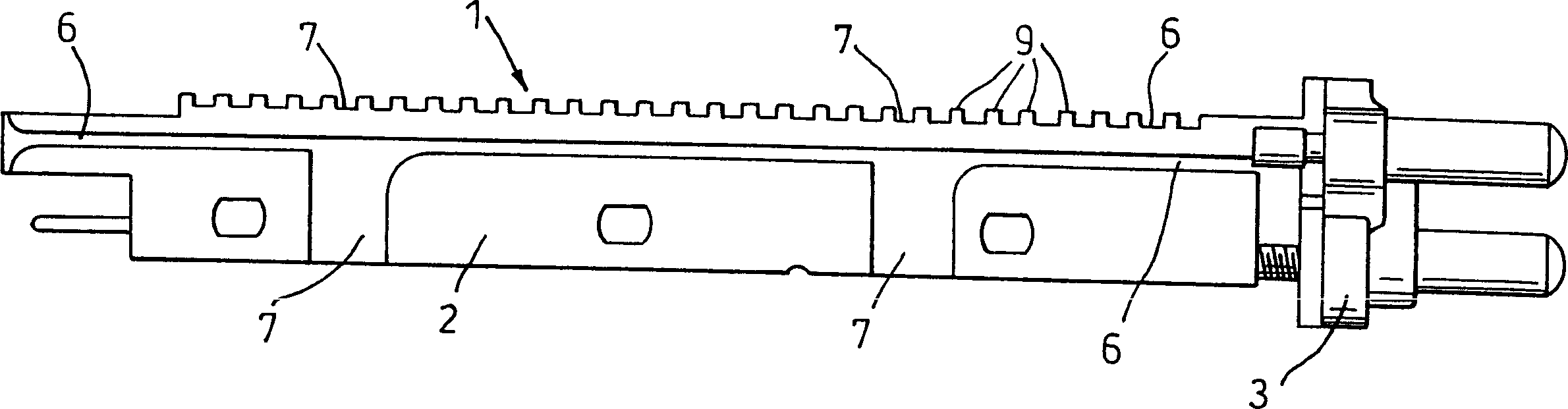
[0031] like Figure 2a and 2b As shown, according to the present invention, a photoelectric module 1 includes a housing 2 , a front cover 3 , and holes 4 and 5 . The casing and the front cover are preferably made of metal materials. However, other suitable materials such as moderately filled and coated polymers may also be used. The housing is provided with a series of fins 9 arranged in rows to act as heat sinks. Channels 4 and 5 provide access to the internal components of the module. In this embodiment, tunnel 4 provides access to an optical signal transmitter (not shown) and tunnel 5 provides access to an optical signal receiver (not shown). Alternatively, tunnel 4 may provide access to the receiver and tunnel 5 may provide communication to the transmitter.

[0032] exist Figure 2a and 2b In the preferred embodiment shown, the channels 4, 5 are of a type adapted to accept optical fibers mated with LC type connectors, but other types of connectors such as SC may als...


PUM


Abstract

The invention relates to a photoelectric module assembly which can be inserted into a DWDM system and detached from the system. This assembly consists of a photovoltaic module (1) provided with a plurality of horizontal grooves (6) and a plurality of vertical slots (7) which allow the insertion of the photovoltaic module in a "drop and install" manner Located in the multiple tabs on the module mount. The present invention also integrates EMI shielding function inside the module.

Description

technical field [0001] The invention relates to an improved photoelectric module assembly applied to a communication or network system. In particular, the present invention relates to an improved fiber optic module that can be inserted into and removed from a communication / network system. Background technique [0002] As the capacity of communication / networking systems increases, so does the need for optical modules that can be inserted and removed from the system without powering down the system. This operation mode is called "hot plugging" in the art. [0003] Moreover, communication / network systems are also trending toward higher levels of integration. This means that users want to be able to add more components and / or modules to the system in as little space as possible. Therefore, there is a need to provide components and modules that can be mounted on user boards with a minimum of board space to obtain maximum density of user board modules. And using less board spa...

Claims


Application Information

Patent Timeline
Patent Type & Authority Patents(China)
IPC IPC(8): G02B6/36G02B6/42H04B10/12
CPCG02B6/4201G02B6/4277G02B6/4261
Inventor 丹尼尔·基布尔克里斯托弗·约翰·奥德贡萨洛·阿格拉·阿莫里姆
Owner BROADCOM INT PTE LTD
Why Eureka
Try Eureka