Anchor cable pressure bowl composite mould

A compound mold and pressure technology, which is applied in the direction of forming tools, manufacturing tools, metal processing equipment, etc., can solve the problems of unfavorable safety production, frequent punching times, low production efficiency, etc., to reduce safety hazards and labor intensity, and high yield , The effect of reducing manufacturing costs

Inactive Publication Date: 2018-11-09
济宁落陵矿山支护材料厂
View PDF0 Cites 0 Cited by
  • Summary
  • Abstract
  • Description
  • Claims
  • Application Information

AI Technical Summary

Problems solved by technology

[0003] In order to solve the current need for two processes in the production of anchor cable pressure bowls, manual operation of the punching machine is frequent, which is not conducive to safe production, and the labor intensity is high, the production efficiency is low, the cost is high, large errors are prone to occur, the process is not accurate, and the cost of parts is high. etc., the present invention provides a composite mold for anchor cable pressure bowl

Method used


Image

  • Anchor cable pressure bowl composite mould
  • Anchor cable pressure bowl composite mould
  • Anchor cable pressure bowl composite mould

Examples


Embodiment Construction

[0021] The specific implementation manners of the present invention will be further described below in conjunction with the accompanying drawings.

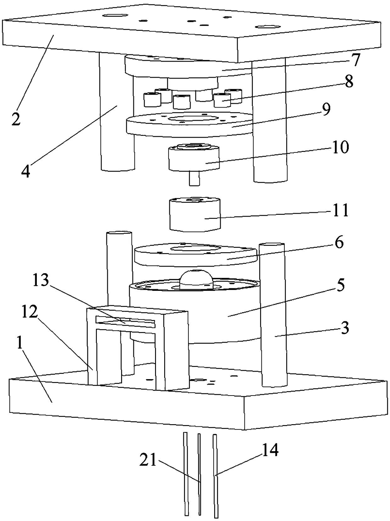
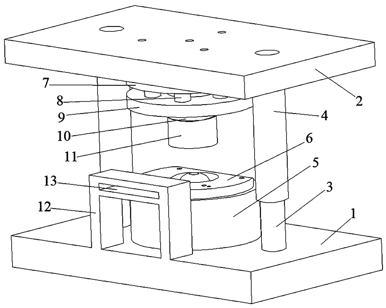
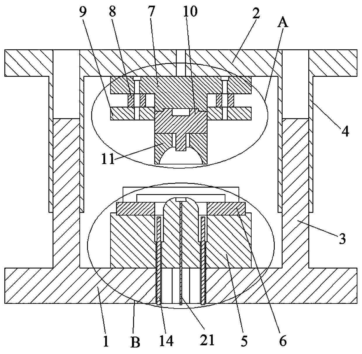
[0022] As shown in the figure, a compound mold for anchor cable pressure bowl includes a rectangular base 1 at the bottom and a rectangular upper seat 2 at the top. The left and right sides of the base 1 are fixed with cylindrical guide posts 3, and the middle part of the base 1 is passed through three bolts. The lower mold 5 of conical shape is installed and fixed, and the upper surface middle part of described lower mold 5 is provided with cylindrical sinking groove 22, and the middle part of sinking groove 22 is integrally formed with cylindrical protruding shaft 19, and the top surface of protruding shaft 19 It has an arc-shaped surface (adapted to the inner surface of the anchor cable pressure bowl), and the center of the top surface of the protruding shaft 19 has a circular inner ring groove 20 (adapted to the middle hole of ...


PUM


Abstract

The invention relates to an anchor cable pressure bowl composite mould and belongs to the field of anchor cable pressure bowl production. The anchor cable pressure bowl composite mould comprises a base and an upper seat; guide columns are fixed to the base; a lower mould is installed at the middle part of the base; a supporting seat is fixed to the lower mould; a cylindrical sinking groove is formed in the lower mould; a bulged shaft is integrally formed in the middle part of the sinking groove; the top surface of the bulged shaft is an arc-shaped surface; an inner ring groove is formed in thecenter of the top surface of the bulged shaft; sleeves fitting with the guide columns are fixed to the upper seat; an upper mould seat is fixed to the lower surface of the upper seat; an upper punching mould is fixed to the lower side of the upper mould seat; a punching rod is integrally formed in the upper punching mould; an upper sleeve mould is fixed to the lower side of the upper punching mould; a circular hole where the punching rod penetrates through is formed in the middle part of the upper sleeve mould; and a concave bowl-shaped cavity is formed in the lower surface of the upper sleeve mould. Through up-and-down squeezing and cutting, punching forming is carried out at one time; the anchor cable pressure bowl composite mould is concise in technology, low in labor intensity, safe,reliable, high in production efficiency and low in production-manufacturing cost; and the anchor cable pressure bowl composite mould is accurate in technology and high in finished product rate, so that the amount of waste pieces can be reduced substantially.

Description

technical field [0001] The invention belongs to the field of anchor cable pressure bowl production, in particular to a composite mold for anchor cable pressure bowls. Background technique [0002] Anchor cable means that when the main cable is anchored in the side hole in the suspension bridge, the main cable should be divided into many strands of steel bundles and anchored in the anchor spindle respectively. These steel bundles are called anchor cables. The anchor cable is fixed on the slope surface through the outer end, and the other end is anchored in the stable rock mass within the sliding surface, passing through the prestressed steel strand on the sliding surface of the slope, directly generating anti-sliding resistance on the sliding surface, increasing the anti-sliding Frictional resistance keeps the structural surface in a compact state to improve the integrity of the rock mass of the slope, thereby fundamentally improving the mechanical properties of the rock mass...

Claims


Application Information

Patent Timeline
Patent Type & Authority Applications(China)
IPC IPC(8): B21D37/10B21D35/00
CPCB21D37/10B21D35/001B21D35/002
Inventor 刘金山张强田尚利刘祥湖
Owner 济宁落陵矿山支护材料厂
Why Eureka
Try Eureka