
Prosthesis for inguinal hernia repair

A groin and prosthesis technology, applied in the field of three-dimensional prosthesis, can solve the problem of not effectively covering the groin area

Active Publication Date: 2018-11-13
SOFRADIM PROD SAS
View PDF7 Cites 0 Cited by
  • Summary
  • Abstract
  • Description
  • Claims
  • Application Information

AI Technical Summary

Problems solved by technology

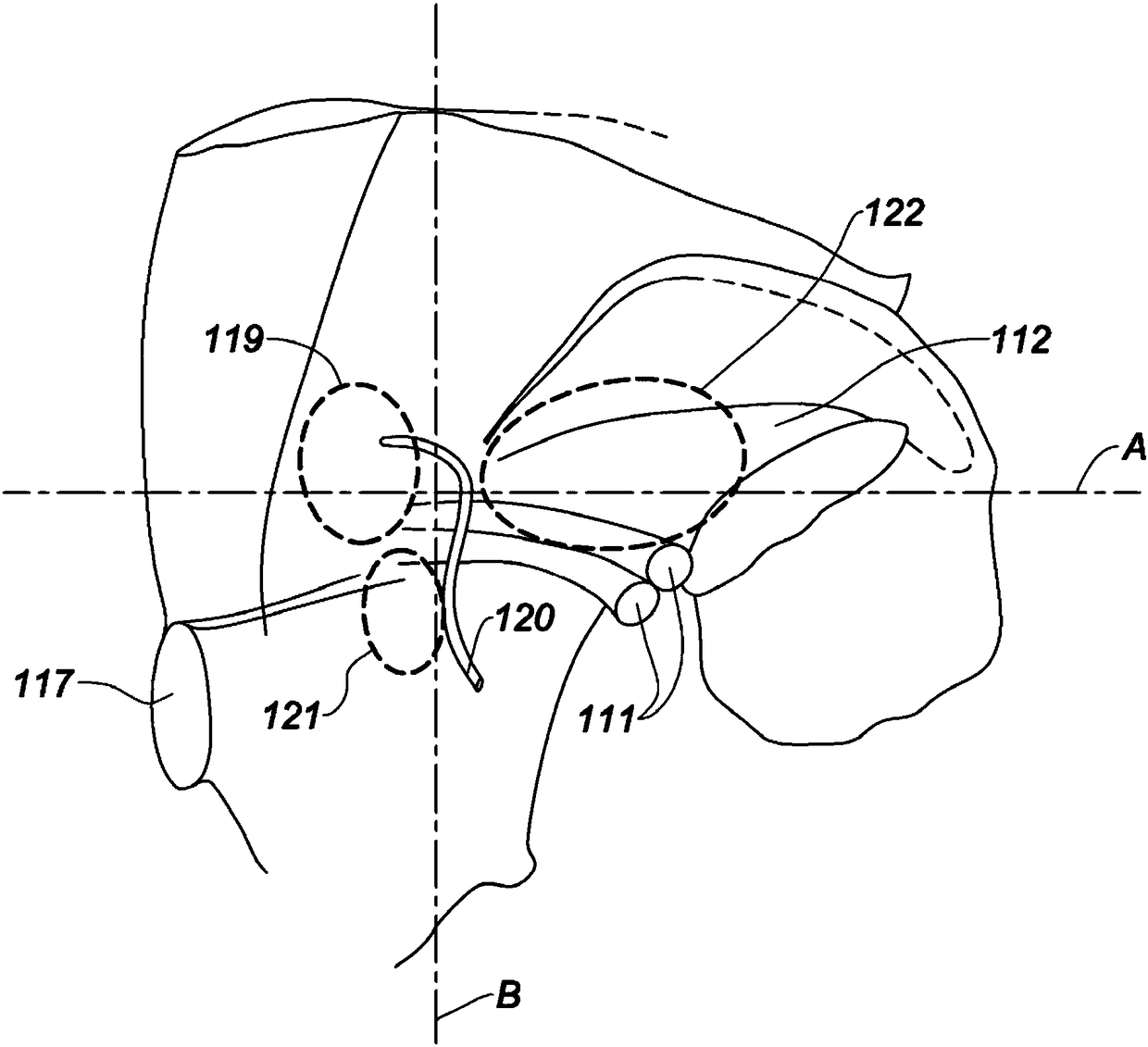
It has been observed that with some preformed 3D prostheses of the prior art, this medial inferior area of ​​the groin area is not effectively covered

Method used


Image

  • Prosthesis for inguinal hernia repair
  • Prosthesis for inguinal hernia repair
  • Prosthesis for inguinal hernia repair

Examples


Embodiment Construction

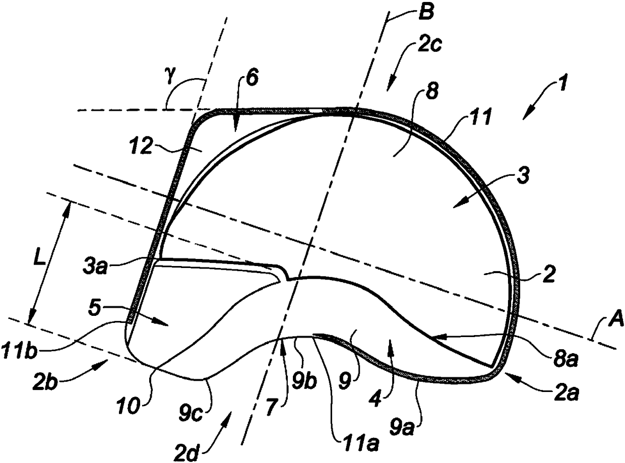
[0067] refer to Figure 2A , presents a prosthesis 1 of the present invention for repairing a hernia defect in the groin area of ​​a human body. figure 1 The prosthesis 1 shown above is intended to be implanted on the left hand side of the patient's body. The prosthesis 1 comprises a piece 2 of biocompatible material having a preformed three-dimensional shape. Figure 2A Upper indicates the medial transverse axis A and the superior inferior axis B. Figure 2A The preformed sheet 2 has a lateral side 2a, an inner side 2b, an upper side 2c and a lower side 2d. Figure 2A Top shows the anterior side of Prosthesis 1.

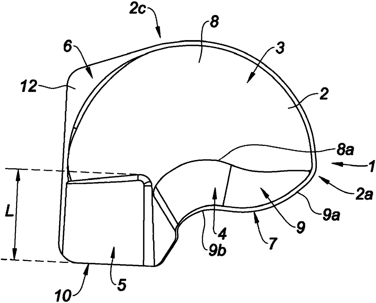
[0068] The sheet 2 comprises a first portion 3 intended to face the front abdominal wall, a second portion 4 intended to face the psoas muscle and a third portion 5 intended to face the medial inferior region of the groin area. In the example shown, the sheet 2 further comprises a fourth portion 6 intended to facilitate the alignment of the prosthesis 1 on the l...


PUM


Abstract

The invention relates to an implantable prosthesis (1) for repairing a hernia defect in an inguinal region, the prosthesis comprising: a piece (2) of biocompatible material having a preformed three-dimensional shape, the piece including: a first portion (3), intended to face the anterior abdominal wall, said first portion forming a partial spherical cap surface (8) shaped and dimensioned so as tosubstantially conform to the shape of the anterior abdominal wall, a second portion (4), intended to face the psoas muscle, said second portion extending from an inferior edge of said first portion and forming a wavy-shaped wall (9), shaped and dimensioned so as to substantially conform to the shape of the psoas muscle, wherein said piece (2) further comprises: a third portion (5) forming an arched part, said arched part extending longitudinally substantially in the inferior direction from a medial inferior comer (3a) of said first portion, said arched part extending radially substantially inthe front direction, said third portion being intended to face the medial inferior area of the inguinal anatomy.

Description

technical field [0001] The present invention relates to a preformed three-dimensional prosthesis for inguinal hernia repair. Background technique [0002] In the present application, an "inside" end or part of an element of a prosthesis is understood to mean an end or part of the element which lies in the direction of the median plane of the human body when the prosthesis is implanted in the human body. A "transverse" end or part of an element of a prosthesis is understood to mean an end or part of an element lying in the direction of an outward transverse plane of the human body when the prosthesis is implanted in the human body. Likewise, in this application, the "inner direction" should be understood as meaning the direction towards the median plane, and the "transverse direction" is opposite to the "inner direction", and the inner direction and the transverse direction are on the same axis - Alignment on medial transverse axis. In this application, an "upper" end or pa...

Claims


Application Information

Patent Timeline
IPC IPC(8): A61F2/00
CPCA61F2/0063A61F2230/0004A61F2230/0023A61F2250/0018A61F2210/0004A61F2210/0071A61F2240/001A61F2230/0063A61F2002/0068
Inventor 皮埃尔·巴伊米莱纳·德索尔姆叙泽莱伊·蒙塔纳里
Owner SOFRADIM PROD SAS
Learn More