
Anti-blockage garbage treatment device

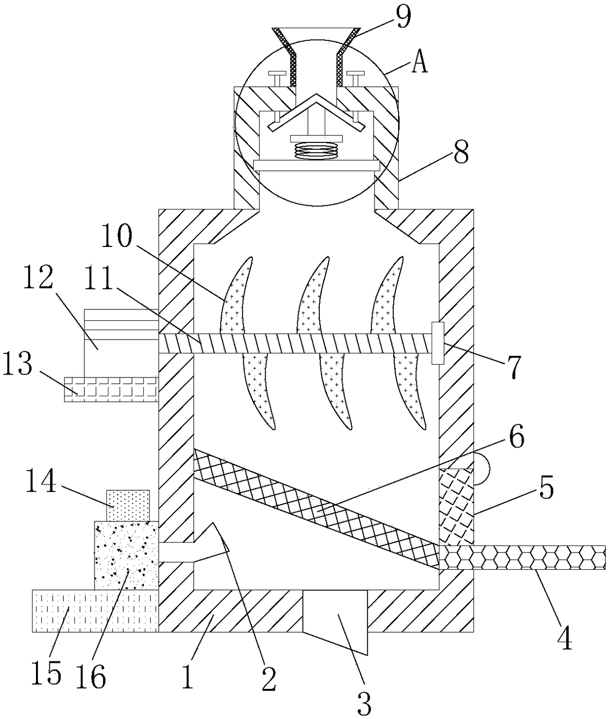
A garbage disposal device and anti-clogging technology, which is applied to heating devices, grain processing, and sieves, can solve the problems of lack of volume control and crushing devices, lack of crushing and mixing steps, and blockage of large pieces of garbage, so as to save water and benefit Effect of incineration and prevention of inlet clogging

Inactive Publication Date: 2018-11-13
FUNAN GAOFUXING INTELLIGENT TECH CO LTD
View PDF1 Cites 2 Cited by
  • Summary
  • Abstract
  • Description
  • Claims
  • Application Information

AI Technical Summary

Problems solved by technology

[0005] The object of the present invention is to provide an anti-clogging garbage disposal device, equipped with volume control and crushing devices, which can prevent the inlet from being blocked due to excessive intake, and can crush large pieces of garbage to prevent it from being blocked at the outlet, and solve the problem of lack of volume control. And the crushing device, when an excessive amount of garbage is put in at one time, it is very easy to form a blockage at the entrance. The lack of crushing and stirring steps in the garbage treatment process will easily cause large pieces of garbage to form a blockage at the exit

Method used


Image

  • Anti-blockage garbage treatment device
  • Anti-blockage garbage treatment device

Examples


Embodiment Construction

[0020] The following will clearly and completely describe the technical solutions in the embodiments of the present invention with reference to the accompanying drawings in the embodiments of the present invention. Obviously, the described embodiments are only some, not all, embodiments of the present invention. Based on the embodiments of the present invention, all other embodiments obtained by persons of ordinary skill in the art without making creative efforts belong to the protection scope of the present invention.

[0021] In describing the present invention, it is to be understood that the terms "center", "longitudinal", "transverse", "length", "width", "thickness", "upper", "lower", "front", " Back", "Left", "Right", "Vertical", "Horizontal", "Top", "Bottom", "Inner", "Outer", "Clockwise", "Counterclockwise", "Axial", The orientation or positional relationship indicated by "radial", "circumferential", etc. is based on the orientation or positional relationship shown in ...


PUM


Abstract

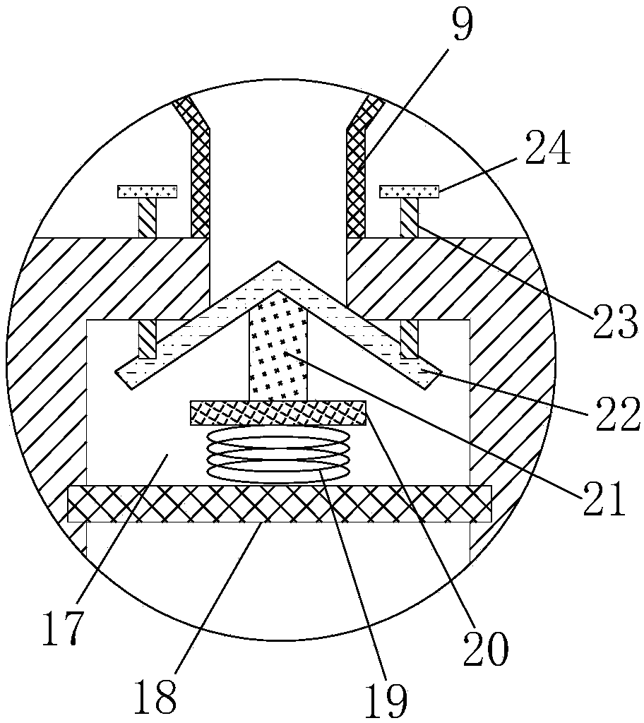
The invention discloses an anti-blockage garbage treatment device. The anti-blockage garbage treatment device comprises a treatment tank. A feeding pipe is arranged in the middle of the top end of thetreatment tank and internally provided with a cavity. A fixing rod is arranged in the middle inside the cavity. The left end and the right end of the fixing rod extend into the two side walls of thecavity correspondingly. A spring is arranged in the middle of the top end of the fixing rod. A movable rod is arranged at the top end of the spring. A connecting pillar is arranged at the top end of the movable rod. An umbrella-shaped plate is arranged at the top end of the connecting pillar. Threaded rods are arranged at the two sides of the top end of the umbrella-shaped plat. The top ends of the two threaded rods penetrate the top wall of the cavity, and a rotary knob is arranged at the end of each threaded rod. The top end of the umbrella-shaped plate is provided with an inlet communicating with the cavity. A side plate is arranged in the middle of the left side of the treatment tank. A motor is arranged at the top end of the side plate. A rotating shaft is coaxially connected to the output end of the motor. The anti-blockage garbage treatment device has the control amount and is provided with a crushing device, and the problem that the inlet is blocked due to excessive feeding canbe prevented; and in addition, massive garbage can be crushed and is prevented from forming blockage at an outlet.

Description

technical field [0001] The invention relates to the technical field of garbage treatment, in particular to an anti-clogging garbage treatment device. Background technique [0002] At present, the domestic waste treatment in our country is generally incinerated after centralized treatment. However, in the process of processing a large amount of waste, the size of the waste is different and the treatment is too much. It affects the efficiency of garbage disposal and causes unnecessary waste. [0003] After searching, the Chinese patent authorization announcement number is CN106801455A, which discloses a kitchen waste treatment device, which includes a shell and a crushing grinder arranged in the shell. Below the crushing grinder, the driving part is connected with the water-repelling plate and the driving part can drive the water-repelling plate to rotate, and the water-repelling plate has a water-repelling block protruding from the lower surface of the water-repelling plate....

Claims


Application Information

Patent Timeline
IPC IPC(8): B02C13/02B02C13/28B02C13/286B02C13/284B07B1/55F26B23/04
CPCB02C13/02B02C13/28B02C13/284B02C13/286B02C2013/28618B02C2023/165B02C2201/06B07B1/55F26B23/04
Inventor 不公告发明人
Owner FUNAN GAOFUXING INTELLIGENT TECH CO LTD
Learn More