Rotational wave nozzle

A technology of nozzles and rotating cylinders, applied in the field of rotating wave nozzles, which can solve the problems of poor drying quality and achieve the effects of prolonged life, high quality and high speed drying

Inactive Publication Date: 2018-11-13
FUJI ELECTRIC CO LTD
View PDF1 Cites 3 Cited by
  • Summary
  • Abstract
  • Description
  • Claims
  • Application Information

AI Technical Summary

Problems solved by technology

Then there is the problem of poor drying quality at high rotational speeds

Method used


Image

  • Rotational wave nozzle
  • Rotational wave nozzle
  • Rotational wave nozzle

Examples


no. 1 approach

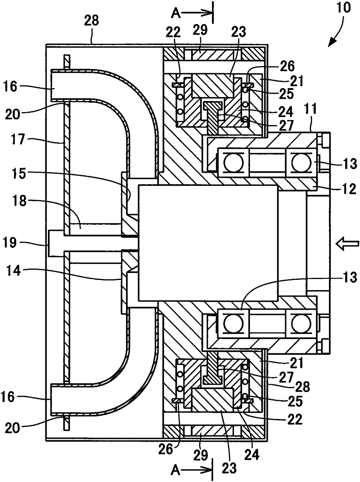
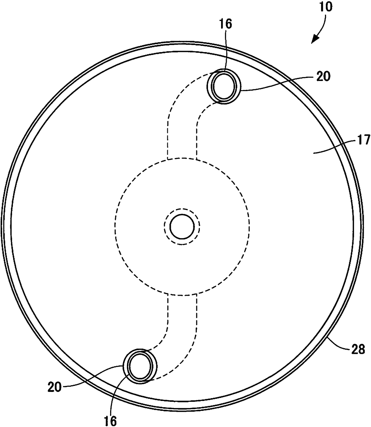
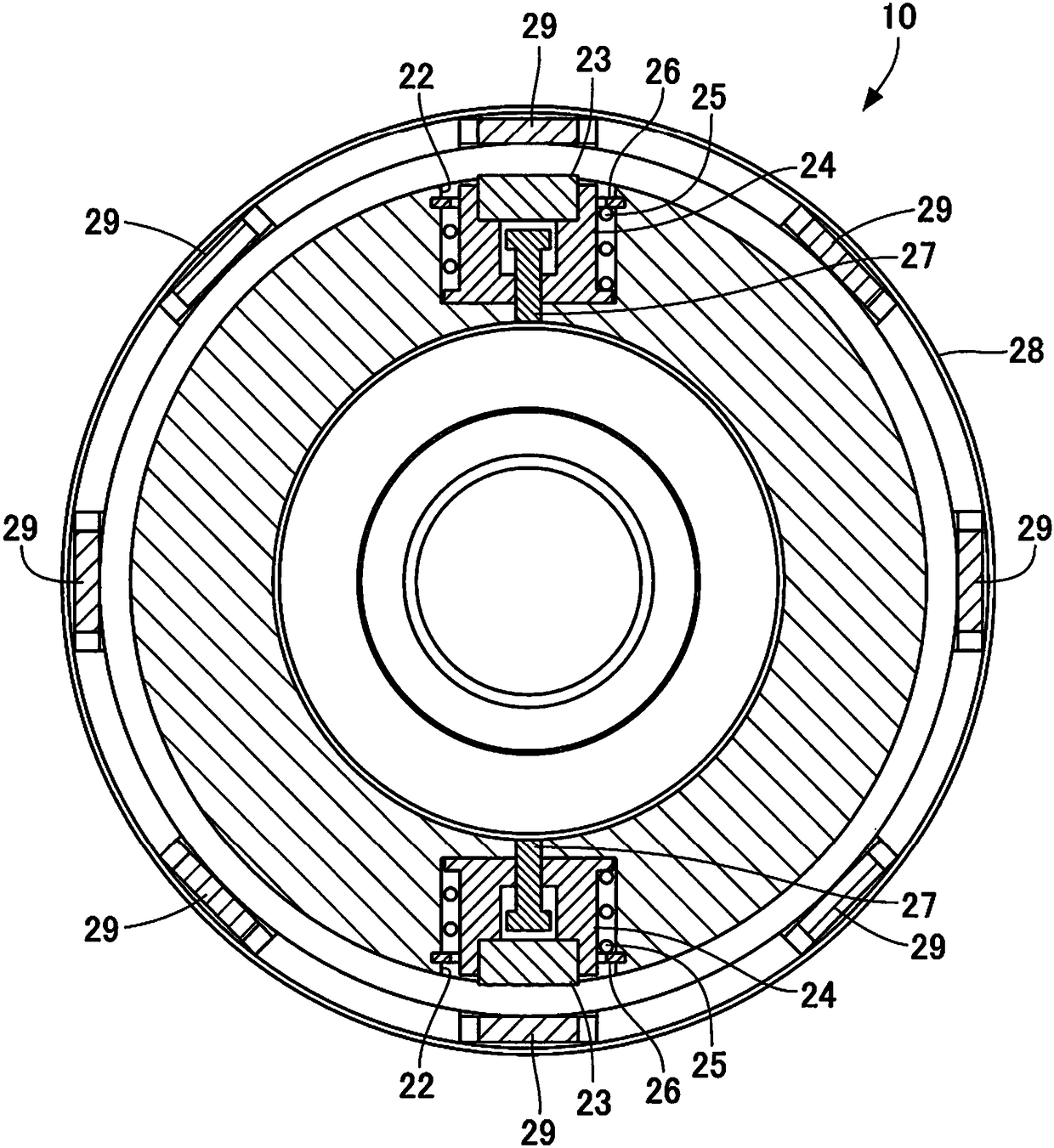
[0036] figure 1 It is a cross-sectional view showing the rotary wave nozzle according to the first embodiment, figure 2 is a side view of the rotating wave nozzle viewed from the jet nozzle side, image 3 is the rotational fluctuation of the nozzle when it is stopped figure 1 A-A sectional view, Figure 4 Indicates the rotating wave nozzle at the time of operation figure 1 A-A to see the sectional view.

[0037] Such as figure 1 As shown, the rotary wave nozzle 10 according to the first embodiment has a hollow cylindrical fixed housing 11 . A hollow cylindrical rotating cylinder 12 is concentrically arranged in the fixed housing 11 , and the rotating cylinder 12 is rotatably supported by two bearings 13 separated in the axial direction inside the fixed housing 11 .

[0038]One end of the rotary cylinder 12 is open, and the other end is closed by an integrally formed closing member 14 . A pipe joint portion 15 is formed at the rotary cylinder 12 on the side closed b...


PUM


Abstract

A rotational wave nozzle. A self-rotating type rotational wave nozzle that prevents the number of rotations from being higher than necessary. In the rotational wave nozzle, a rotary cylinder is supported by two bearings provided separately in an axial direction inside a fixed housing such that the rotary cylinder is freely rotatable. A spray nozzle is connected to the rotary cylinder, and the rotary cylinder is self-rotated through inclinedly ejecting compressed air supplied to a hollow section of the rotary cylinder relative to a surface of a disc. An annular member is provided to the rotarycylinder, movable attraction members being movable in a radial direction and being urged inward in the radial direction by a biasing member are installed at an outer periphery of the annular member, and fixed attraction members are installed on an inner wall of a protective cover and arranged in a circumferential direction so as to face the mobile attraction member. As the number of rotations of the rotary cylinder increases, the mobile attraction members approaching the fixed attraction members increase the mutual attractive force, and the number of rotations of the rotary cylinder decreasesand therefore does not exceed the prescribed number of rotations.

Description

technical field [0001] The invention relates to a rotary wave nozzle which intermittently blows fluid to workpieces. Background technique [0002] An air gun is known as a device for blowing fluid to a workpiece. The air gun sprays compressed air and blows the injected compressed air to the wet-cleaned workpiece to blow off liquid droplets, thereby drying the workpiece. This type of air gun is also used in the shipping process of semiconductor chips. That is, in the shipping process of semiconductor chips, for example, use a warm water bath to clean the trays that transport and protect the semiconductor chips to be shipped, blow compressed air to the wet trays with an air gun to blow off droplets, and place the trays in a dry place. oven to dry it. [0003] In the blow drying method using an air gun, there is a phenomenon that the droplets crawl on the surface of the tray or go around to the back. Therefore, in the drying with the air gun, the liquid droplets remaining on...

Claims


Application Information

Patent Timeline
Patent Type & Authority Applications(China)
IPC IPC(8): B05B3/02B05B1/00
CPCB05B1/005B05B3/02B08B5/02B05B3/06B05B3/003
Inventor 清水均
Owner FUJI ELECTRIC CO LTD
Why Eureka
Try Eureka