
Machining technology of tubular mold inner hole of stepped hole

A processing technology and step hole technology, which is applied in the processing technology field of the inner hole of the step hole tube mold, can solve the problems of different axis of the inner hole, excessive tolerance, easy boring and deviation, etc., so as to reduce the wall thickness difference of the tube mold. , Improve product processing quality and ensure the effect of coaxiality requirements

Active Publication Date: 2018-11-13
HENAN ZHONGYUAN SPECIAL STEEL EQUIP MFG CO LTD
View PDF8 Cites 12 Cited by
  • Summary
  • Abstract
  • Description
  • Claims
  • Application Information

AI Technical Summary

Problems solved by technology

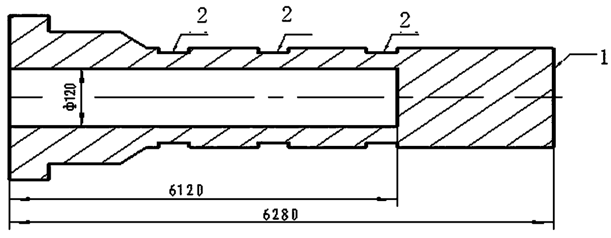
[0002] processed as figure 1 The inner hole of the pipe mold shown is a stepped hole. In the past, this kind of deep hole was processed on a deep hole drilling and boring machine. Drilling from the non-marking end, drilling a φ100mm through hole, and then boring from the non-marking end φ120mm, because the length of the workpiece is 6-7 meters, when drilling the bottom hole φ100mm, the drill pipe used is thin and has poor rigidity, which may easily cause the exit deviation, and it is easy to bore deviation when boring the hole again, resulting in the inner hole being out of axis, and the intersection of the two holes. Large staggering and wall thickness difference. If the staggering is large or the wall thickness difference is too large (the drawing requires a wall thickness difference ≤ 3mm), the workpiece will be scrapped. In view of this, we urgently need to design a tube for processing this step hole. A New Technology of Hole in Mold

Method used


Image

  • Machining technology of tubular mold inner hole of stepped hole
  • Machining technology of tubular mold inner hole of stepped hole

Examples


Embodiment Construction

[0014] Such as figure 1 Shown discloses a workpiece with the inner hole of the stepped hole pipe mold, and also discloses a processing technology for the inner hole of the stepped hole pipe mold. figure 1 For the inner hole of the workpiece as shown, first drill from the non-marked end on the deep hole drilling and boring machine, drill a φ120 blind hole, and ensure a length of 6120mm; The top bears against the inner hole of the non-marking end of the workpiece, figure 2 There are three rack positions 2 on the vehicle shown in the position. The distance between rack position 2 and the end face of marking end 1 is 160mm, 3000mm, and 5800mm respectively, and the length of the rack position is 150mm. The wall thickness difference at the position of the adjustment frame is ≤1.5mm, and the outer circle is left with a machining allowance of 7mm for rough turning of the outer circle. Then go to the deep hole drilling and boring machine, align the outer circle of the workpiece, cla...


PUM


Abstract

The invention relates to a machining technology of a tubular mold inner hole of a stepped hole capable of guaranteeing coaxiality of the stepped inner hole of the tubular mold. The technology comprises the following steps that a blind hole with Phi 120 mm is drilled at first, due to the fact that the drill rod is fine, the drill rod extrudes long, the axis of the hole is deviated, and the disalignment is existed between the axis of the hole and the axis of the tubular body of the tubular mold; an upper lathe is used for adjusting a wall thickness difference to be smaller than or equal to 1.5 mm through the lathe frame positions; then the outer circle is lathed; the thickness difference of the full-length of a workpiece can be ensured to be less than or equal to 1.5 mm, and aligning is carried out on the workpiece according to the outer circle on a deep hole drilling and boring machine; and the holes of Phi 100 mm are drilled oppositely, the length of the holes of Phi 100 mm are shorter, the axis of the hole does not deflect, so that the inner hole coaxiality requirement of the stepped inner hole of the tubular mold is guaranteed, the wall thickness difference of the tubular mold isreduced, and the product machining quality is improved.

Description

technical field [0001] The invention belongs to the technical field of mechanical processing, and in particular relates to a processing technology for the inner hole of a stepped hole pipe mold which can ensure the coaxiality requirement of the stepped inner hole of the pipe mold. Background technique [0002] processed as figure 1 The inner hole of the pipe mold shown is a stepped hole. In the past, this kind of deep hole was processed on a deep hole drilling and boring machine. Drilling from the non-marking end, drilling a φ100mm through hole, and then boring from the non-marking end φ120mm, because the length of the workpiece is 6-7 meters, when drilling the bottom hole φ100mm, the drill pipe used is thin and has poor rigidity, which may easily cause the exit deviation, and it is easy to bore deviation when boring the hole again, resulting in the inner hole being out of axis, and the intersection of the two holes. Large staggering and wall thickness difference. If the ...

Claims


Application Information

Patent Timeline
Patent Type & Authority Applications(China)
IPC IPC(8): B23P15/00B23P15/24
CPCB23P15/00B23P15/24
Inventor 赵玉赵东
Owner HENAN ZHONGYUAN SPECIAL STEEL EQUIP MFG CO LTD
Learn More