Supercharge Your Innovation With Domain-Expert AI Agents!

Building concrete mixer

A technology for concrete mixers and construction, applied in the field of concrete mixing, can solve the problems of reducing the mixing quality and cleaning the inner wall of the mixer, etc.

Inactive Publication Date: 2018-11-13
张建玉
View PDF0 Cites 1 Cited by
  • Summary
  • Abstract
  • Description
  • Claims
  • Application Information

AI Technical Summary

Problems solved by technology

For a concrete mixer, the viscosity of the concrete will become higher and higher during the process of the concrete being mixed by the mixer; the concrete will often adhere to the inner wall of the mixer because of its high viscosity, and the stirring screw may not be able to touch the wall, making it difficult to attach When the concrete on the inner wall is mixed, even if the concrete mixed by the mixer is poured out, the concrete attached to the inner wall of the mixer will not easily fall off. Once the concrete attached to the inner wall of the mixer solidifies, it will affect the mixing of the mixer. Efficiency reduces the mixing quality, and it also causes trouble to clean the inner wall of the mixer

Method used


Image

  • Building concrete mixer
  • Building concrete mixer
  • Building concrete mixer

Examples


specific Embodiment approach

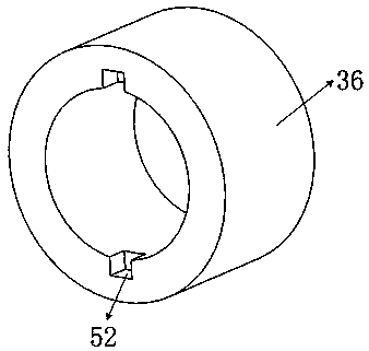
[0076] Specific implementation method: before the mixer is ready to mix concrete, the feed port ring shell 5 faces upwards and the feed port ring shell 5 is connected with the charging mechanism; the first spring 49 is not stretched, and the two limit plates 50 on the rotating rod 37 They are respectively located in the two limiting grooves 52 of the second support ring 36 ; the slider spring 31 is always in a compressed state, and the slider 30 is located at the end of the guide rail 27 away from the first rotating shaft 9 .

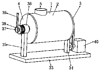
[0077] When the mixer is mixing concrete, the raw materials of the concrete enter the mixing space 55 through the charging mechanism and the material opening ring shell 5; then start the reduction motor 40, and the reduction motor 40 drives the first pulley 43 to rotate through the drive shaft 44, and the first pulley 43 passes through The belt 42 drives the second pulley 6 to rotate, and the second pulley 6 drives the first rotating shaft 9 to rotate. ...


PUM


Abstract

The invention belongs to the technical field of concrete mixing, and particularly relates to a building concrete mixer. The building concrete mixer comprises a mixing mechanism, a base, a speed reduction motor, a belt, a first belt wheel and the like. A lock structure is composed of a handle plate, a third ring sleeve, a rotation rod, a fixing ring disc, a clamping ring, a connecting ring, a fixing ring, a first spring, a limiting plate and a second supporting ring sleeve, and the lock structure can achieve barrel shell rotation. In the concrete mixing process, a material port ring shell is arranged upwards. When unloading is needed, a barrel shell rotates, and the material port ring shell is arranged downwards. For the mixing mechanism, after a first rotation shaft is subjected to a series of transmission, a spiral sheet can be made to revolve around the axis of the first rotation shaft; when a first gear is fixed and a second gear rotates around the outer gear face of the first gear,the second gear can rotate by itself, and accordingly the spiral sheet is driven to rotate by itself after the second gear is subjected to a series of transmission; and finally, the spiral sheet canmix concrete in the mixing space.

Description

technical field [0001] The invention belongs to the technical field of concrete mixing, in particular to a concrete mixer for construction. Background technique [0002] At present, the technology of concrete mixing is mainly used in the field of construction, and plays a very important role in the construction of buildings such as industry, agriculture, transportation, national defense, water conservancy, and municipal administration. Concrete mixer is a common machine that uses concrete mixing technology. It is a machine that mixes cement, sand and gravel aggregates and water and mixes them into concrete mixtures. For a concrete mixer, the viscosity of the concrete will become higher and higher during the process of the concrete being mixed by the mixer; the concrete will often adhere to the inner wall of the mixer because of its high viscosity, and the stirring screw may not be able to touch the wall, making it difficult to attach When the concrete on the inner wall is m...

Claims


Application Information

Patent Timeline
Patent Type & Authority Applications(China)
IPC IPC(8): B28C5/14
CPCB28C5/142
Inventor 张建玉
Owner 张建玉
Features
  • R&D
  • Intellectual Property
  • Life Sciences
  • Materials
  • Tech Scout
  • Unparalleled Data Quality
  • Higher Quality Content
  • 60% Fewer Hallucinations
Learn More