Supercharge Your Innovation With Domain-Expert AI Agents!

Building cement mixing device

A technology of mixing device and building cement, applied in cement mixing device, control device, unloading device, etc., can solve the problems of raw materials not meeting the requirements, slow mixing speed, slow mixing speed, etc., to achieve convenient operation and improve cement quality , to avoid the effect of cracking

Inactive Publication Date: 2018-12-14
浙江天姥建设发展有限公司
View PDF9 Cites 1 Cited by
  • Summary
  • Abstract
  • Description
  • Claims
  • Application Information

AI Technical Summary

Problems solved by technology

The traditional cement mixing device has the disadvantages of slow stirring speed, slow mixing speed, low uniformity, and troublesome feeding, which makes the raw materials fail to meet the requirements after mixing, which brings great inconvenience to the production of enterprises.

Method used


Image

  • Building cement mixing device
  • Building cement mixing device
  • Building cement mixing device

Examples


Embodiment 1

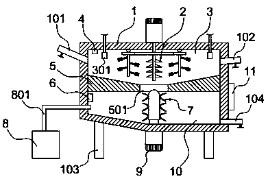
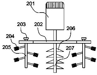
[0035] Such as Figure 1-3 As shown, a building cement mixing device includes a mixing box 1 connected to a support column 103 at the bottom, and the inside of the mixing box 1 is divided into a mixing chamber 3 and a discharge chamber 10 up and down by a partition plate 501, and a flow hole is provided in the middle of the partition plate 501 501, the stirring chamber 3 is provided with a stirring mechanism 2, the stirring box 1 on both sides of the stirring chamber 3 is respectively provided with a feed pipe 101 and a liquid inlet pipe 102, and the bottom of the discharge chamber 10 is connected with a discharge pipe whose outlet is located outside the stirring box 1 The material pipe 104 is connected to the industrial computer 11 on the outer wall of the mixing box 1 , the humidity detector 4 is connected to the top wall of the mixing chamber 3 , and the temperature detector 6 is connected to the side wall of the discharge chamber 10 . The mixing chamber 3 and the discharge...

Embodiment 2

[0044] Such as Figure 4 Shown, a kind of using method of construction cement mixing device comprises the following steps:

[0045] S1: Input cement mixing parameters into the industrial computer 11, such as raw materials and dosage for cement mixing, cement mixing time, mixing speed of each mixing component, etc.;

[0046] S2: preparing cement mortar, sending cement, sand and water into the mixing chamber 3 for mixing;

[0047] S3: the industrial computer 11 reads the parameters of the temperature detector 6 and the humidity detector 4 in the mixing box 1;

[0048] S4: the industrial computer 11 optimizes the stirring parameters using a calculation program;

[0049] S5: preparing cement concrete mixture, sending crushed stone and water into the mixing chamber 3 for mixing;

[0050] S6: discharge, end the program. During the mixing process, the operating parameters of each component are controlled by the industrial computer 11, and the monitoring parameters of the humidity...


PUM


Abstract

The invention discloses a building cement mixing device and belongs to the field of building equipment. The building cement mixing device comprises a mixing box, wherein the lower part of the mixing box is connected with support columns; inside of the mixing box is divided into a mixing chamber and a discharging chamber through a separation board; a circulation hole is formed in the middle of theseparation board; a mixing mechanism is arranged in the mixing chamber; a material feed pipe and a liquid feed pipe are arranged on the mixing box on two sides of the mixing chamber respectively; a discharge pipe with the outlet formed outside the mixing box is connected with the bottom of the discharging chamber; an industrial personal computer is connected to the outer wall of the mixing box; ahumidity detector is connected to the top wall of the mixing chamber; a temperature detector is connected to the side wall of the discharging chamber. The building cement mixing device is high in cement mixing speed and high in mixing uniformity, quality of finished cement products is high, mixing parameters are detected by the industrial personal computer, the mixing parameters are optimized in the mixing process and the cement mixing effect is improved.

Description

technical field [0001] The invention belongs to the field of construction equipment, and in particular relates to a construction cement mixing device. Background technique [0002] The cement mixing device is a machine with a shaft with blades that rotates in a cylinder or a tank to stir and mix various raw materials to make it a mixture or a suitable consistency. There are many kinds of cement mixing devices, such as forced cement mixing device, single horizontal shaft cement mixing device, twin horizontal shaft cement mixing device and so on. The traditional cement mixing device has the disadvantages of slow stirring speed, slow mixing speed, low uniformity, and troublesome feeding, which makes the raw materials fail to meet the requirements after mixing, which brings great inconvenience to the production of enterprises. Contents of the invention [0003] The object of the present invention is to provide a construction cement mixing device with fast cement mixing speed,...

Claims


Application Information

Patent Timeline
Patent Type & Authority Applications(China)
IPC IPC(8): B28C5/08B28C5/16B28C7/16B28C7/02
Inventor 丁淮君
Owner 浙江天姥建设发展有限公司
Features
  • R&D
  • Intellectual Property
  • Life Sciences
  • Materials
  • Tech Scout
  • Unparalleled Data Quality
  • Higher Quality Content
  • 60% Fewer Hallucinations
Learn More