Self-adjustment type nozzle assembly for full encapsulation mold

A fully encapsulated and self-adjusting technology, applied in the field of self-adjusting nozzle assemblies for fully encapsulated molds, can solve the problems of affecting quality, unable to achieve regional adjustment, affecting appearance, etc., and achieve the effect of ensuring the upper and lower pressure values.

Active Publication Date: 2018-11-13
NANTONG UNIVERSITY +1
View PDF6 Cites 0 Cited by
  • Summary
  • Abstract
  • Description
  • Claims
  • Application Information

AI Technical Summary

Problems solved by technology

For this kind of operation, the lead frame connected with the chip is usually placed in a full-encapsulation mold for plastic packaging. Usually, the lead frame is placed on the center line, the cavity is divided into upper and lower layers, and the injection nozzle is used to inject into the cavity. Plastic sealant, the plastic sealant is divided into upper and lower two ways to enter the top and bottom of the lead frame for overall plastic sealing. The existing nozzles are all square outlets, and the glue is directly injected into the mold cavity, and the pressure value and speed value of the injection are constant. It is impossible to achieve regional adjustment, which makes the pressure value of the colloid above the lead frame larger than that of the bottom (the colloid is liquid and has a certain gravity), which will make the location of the lead frame cheaper, even because of the amount of glue injected. Inconsistency leads to air holes in the plastic after packaging, which affects the subsequent quality. In order to ensure the levelness of the lead frame, ejector pins are usually set in the lower mold for auxiliary support. Although it can play a certain role, a small amount of deviation will still occur due to excessive pressure difference The situation, and the setting of the thimble needs to be extracted in time when the upper and lower ends of the colloid are closed, so as to prevent the thimble from being screwed inside, or because the extraction time is over, a working hole will be left at the closure, which will affect the appearance.

Method used


Image

  • Self-adjustment type nozzle assembly for full encapsulation mold
  • Self-adjustment type nozzle assembly for full encapsulation mold
  • Self-adjustment type nozzle assembly for full encapsulation mold

Examples


Embodiment Construction

[0018] The technical solutions of the embodiments of the present invention will be clearly and completely described below in conjunction with the accompanying drawings of the present invention.

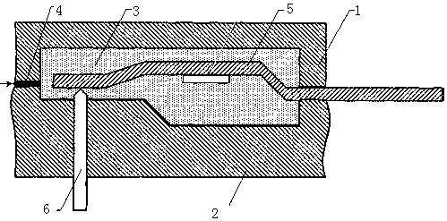
[0019] Such as Figure 1~5 As shown, a self-adjusting nozzle assembly for a fully encapsulated mold disclosed in this embodiment, the structure of the fully encapsulated mold includes an upper mold 1 and a lower mold 2, and a glue injection cavity 3 is formed inside after the mold is closed. And form a glue injection port 4 at the front end, the lead frame 5 is placed in the glue injection cavity, and is supported by the thimble 6 inserted in the lower mold to ensure that it is horizontal and located at the mold line of the upper mold and the lower mold.

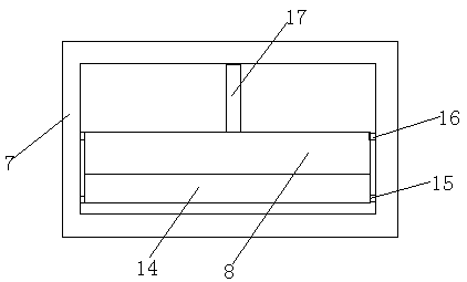
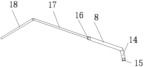
[0020] One end of the nozzle assembly is installed at the front end of the L-shaped rubber hose, and the other end is inserted into the glue injection port 4. The specific nozzle assembly includes a glue spray pipe 7 and an adjustin...


PUM


Abstract

The invention discloses a self-adjustment type nozzle assembly for a full encapsulation mold. The self-adjustment type nozzle assembly comprises a glue spray pipe and an adjusting baffle. The sectionof the glue spray pipe is square, and the glue spray pipe is arranged at the front end of a glue pipe in a sleeving manner. Adjusting grooves and inserting holes are formed in the two opposite end faces of the inner wall of the glue spray pipe, and a connecting rod is fixed between the two side walls of the glue spray pipe. A supporting plate is mounted in the center of the rear end face of the connecting rod and is perpendicular to the connecting rod. Protruding clamp columns are arranged on the two sides of the rear end of the adjusting baffle, and the center of the rear end face of the adjusting baffle extends to form a rod body. A trigger rod is hinged to the end of the rod body. The adjusting baffle is clamped in the inserting holes of the glue spray pipe through the clamp columns onthe two sides, the rod body at the rear end and the trigger rod are located in the glue pipe, and the bottom of the trigger rod abuts against the supporting plate. The adjusting baffle rotates with the clamp columns as the center, and switching of the inclined state and the horizontal state of the adjusting baffle is achieved.

Description

technical field [0001] The invention relates to an all-encapsulation mold, in particular to a self-adjusting nozzle assembly for an all-envelopment mold. Background technique [0002] At present, microelectronic chip-level packaging mainly includes wire bonding (Wire Bonding), flip chip (Flipchip), through-silicon via (TSV, Through-Silicon-Via) and other processes, of which Wire Bonding still occupies a relatively large proportion. After packaging using the Wire Bonding process, it is generally necessary to provide additional plastic protection for the chip and gold wire / copper wire / aluminum wire. For this kind of operation, the lead frame connected with the chip is usually placed in a full-encapsulation mold for plastic packaging. Usually, the lead frame is placed on the center line, the cavity is divided into upper and lower layers, and the injection nozzle is used to inject into the cavity. Plastic sealant, the plastic sealant is divided into upper and lower two ways to ...

Claims


Application Information

Patent Timeline
Patent Type & Authority Applications(China)
IPC IPC(8): B29C45/20
CPCB29C45/20
Inventor 王强宋帅迪仝进峰陈云顾贤马建东
Owner NANTONG UNIVERSITY
Why Eureka
Try Eureka