
Mold assembly

A component and mold technology, applied in the field of mold components, can solve problems such as the inability to meet the needs of structural design

Pending Publication Date: 2018-11-13
OPD TECH SHENZHEN
View PDF0 Cites 0 Cited by
  • Summary
  • Abstract
  • Description
  • Claims
  • Application Information

AI Technical Summary

Problems solved by technology

[0004] The purpose of the present invention is to provide a mold assembly to solve the technical problem in the prior art that the plastic accessories used to be installed at the USB hole of the mobile phone head cannot meet the structural design requirements according to the traditional production method

Method used


Image

  • Mold assembly
  • Mold assembly
  • Mold assembly

Examples


Embodiment Construction

[0029] In order to make the technical problems, technical solutions and beneficial effects to be solved by the present invention clearer, the present invention will be further described in detail below in conjunction with the accompanying drawings and embodiments. It should be understood that the specific embodiments described here are only used to explain the present invention, not to limit the present invention.

[0030] It should be noted that when an element is referred to as being “fixed” or “disposed on” another element, it may be directly on the other element or be indirectly on the other element. When an element is referred to as being "connected to" another element, it can be directly connected to the other element or indirectly connected to the other element.

[0031] It is to be understood that the terms "length", "width", "top", "bottom", "front", "rear", "left", "right", "vertical", "horizontal", "top" , "bottom", "inner", "outer" and other indicated orientations...


PUM


Abstract

The invention provides a mold assembly and belongs to the technical field of injection molding. The mold assembly comprises a mold main body provided with a mold cavity and an aluminum insert which accommodated in the mold cavity and is provided with a step lug. The mold assembly also comprises an inner slide block which comprises a barb part stretching right below the step lug and an embedding groove which retracts reversely relative to the extending direction of the barb part, wherein the upper surface where the embedding groove is formed and the horizontal plane form a first angle, the lower surface where the embedding groove is formed and the horizontal plane form a second angle, and the first angle is smaller than the second angle; the mold assembly also comprises a pushing assembly for pushing the inner slide block to be far away from or close to the step lug along the direction, forming a third angle, with the horizontal plane; the third angle is greater than the first angle butsmaller than the second angle. Only by changing the bottom surface of a projecting tongue to a plane, forming the second angle, with the horizontal plane, other all structural demands of a plastic accessory can be met. The bottom surface of the projecting tongue is a non-functional surface of the whole plastic accessory, so that use and assembly of the plastic accessory are not affected.

Description

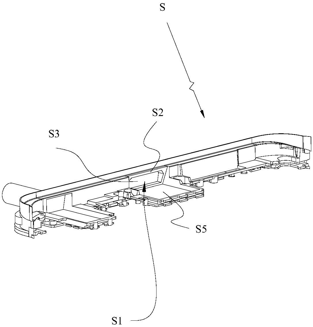
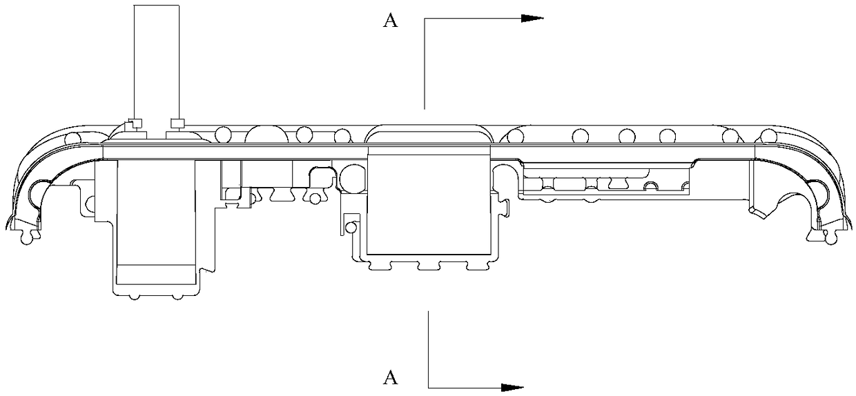
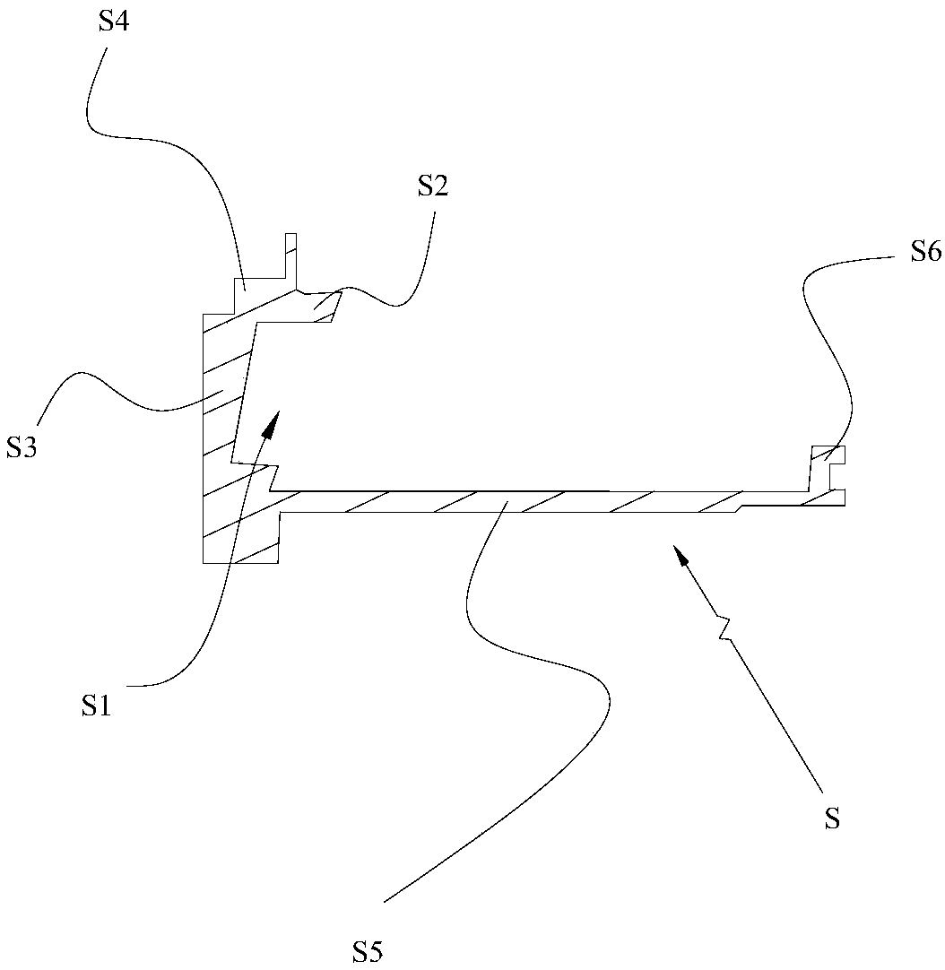
technical field [0001] The invention belongs to the technical field of injection molding, and more specifically relates to a mold assembly. Background technique [0002] In the existing mobile phone structure, there is a plastic accessory used to be installed at the USB hole on the head of the mobile phone, which is hereinafter referred to as the plastic accessory S. The plastic accessory S is mostly made by injection molding. In a mobile phone, the plastic accessory S needs to be made as Figure 1 to Figure 3 In the shown structure, an inner buckle groove S1 is provided in the middle of its width direction. The inner buckle groove S1 is connected to the tongue S2 and the front plate body S3 on the front side by the tongue S2 on the upper side. The stepped portion S4 between the front plate body S3 and the bottom plate S5 on the lower side are enclosed and formed, and a raised portion S6 is also provided on the end of the bottom plate S5 opposite to the inner buckle groove S...

Claims


Application Information

Patent Timeline
Patent Type & Authority Applications(China)
IPC IPC(8): B29C45/26B29C45/33B29C45/44B29L31/34
CPCB29C45/26B29C45/33B29C45/44B29L2031/3437
Inventor 肖勇匡小吉钟元养
Owner OPD TECH SHENZHEN
Learn More