Safety protection device of railroad platform door

A safety protection device and platform door technology, which is applied to railway car body components, roads, stations, etc., can solve the problems of complex structure of the device and high construction cost, and achieve the effects of expanding the scope of application, reducing construction costs, and avoiding congestion

Inactive Publication Date: 2018-11-13
西安安源智造机电设备有限公司
View PDF6 Cites 3 Cited by
  • Summary
  • Abstract
  • Description
  • Claims
  • Application Information

AI Technical Summary

Problems solved by technology

[0004] The purpose of the present invention is: in order to solve the problems of complex device structure and high construction cost in the prior art when solving the problem of passenger safety protection at the platform door, the present invention provides a safety protection device for railway platform doors

Method used


Image

  • Safety protection device of railroad platform door
  • Safety protection device of railroad platform door
  • Safety protection device of railroad platform door

Examples


Embodiment 1

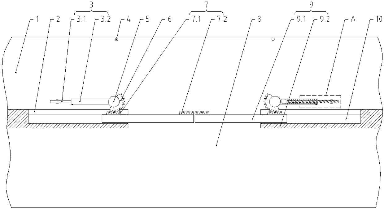
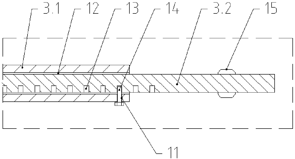
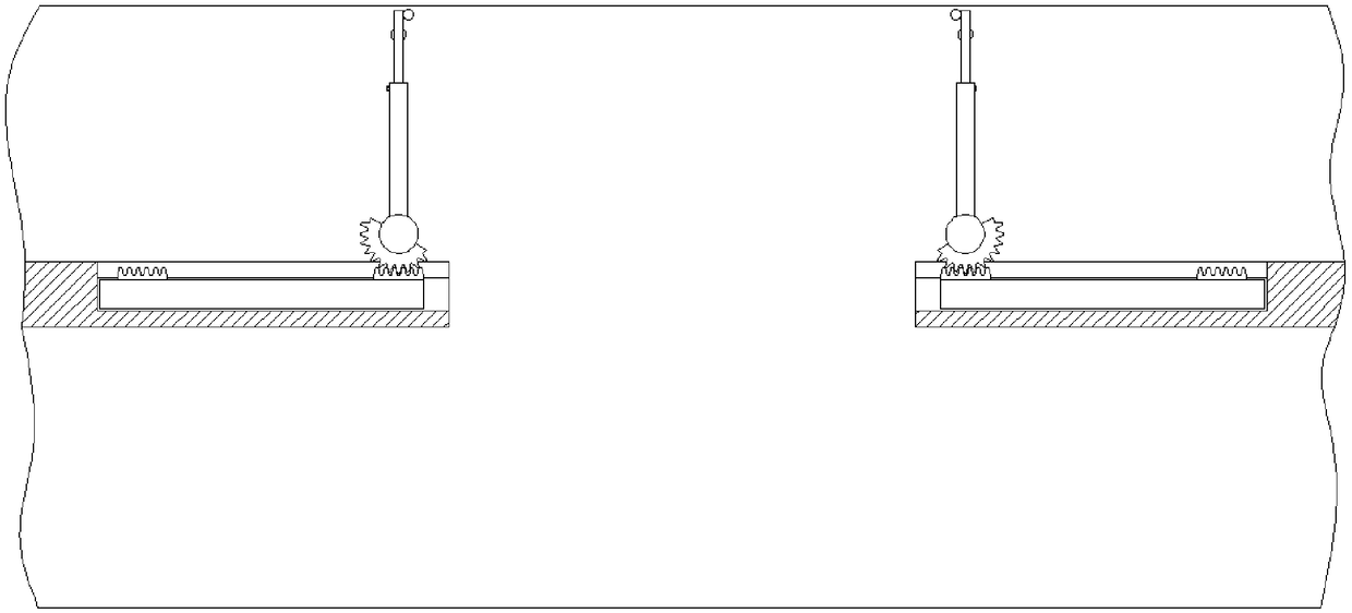
[0025] A safety protection device for a railway platform door, comprising a platform door 9, which divides the platform into a waiting area 8 and a boarding area 1, and the platform door 9 includes fixed parts 9.2 on both sides and sliding doors 9.1 set on the fixed part 9.2 The fixed part 9.2 is provided with an installation groove 10 for accommodating the sliding door 9.1, the surface of the fixed part 9.2 located on the side of the boarding area 1 is horizontally provided with a strip opening 2 connected with the installation groove 10, and the surface of the sliding door 9.1 is horizontally provided with a The rack mechanism 7 corresponding to the strip-shaped opening 2 is provided with a rotatable column 5 near the notch of the installation groove 10 on the boarding area 1, and a surface on one side of the column 5 is provided to cooperate with the rack mechanism 7 through the strip-shaped opening 2. The half gear 6, the other side surface of the column 5 is fixed with a b...

Embodiment 2

[0030] This embodiment improves on the basis of Embodiment 1:

[0031] The rack mechanism 7 is divided into a rack a7.1 and a rack b7.2 respectively fixed on two ends of the sliding door 9.1, and the rack a7.1 and the rack b7.2 can mesh with the half gear 6.

[0032] Working principle: when the sliding door 9.1 moves to open and close, the rack a7.1 and the rack b7.2 respectively cooperate with the half gear 6 to drive its rotation, and the rack a7.1 and the rack b7.2 drive the half gear 6 The total angle of rotation is 90°. Among them, when the sliding door 9.1 is closed, the baffle plate 3 is in a storage state parallel to the fixed part 9.2, and the rack a7.1 keeps meshing with the half gear 6; 9.2 In the vertical working state, the rack b7.2 keeps meshing with the half gear 6 at this moment.

[0033] The advantage of the above improvement is that when the sliding door and the baffle are in two different states synchronously, the rack a and the rack b respectively maintai...

Embodiment 3

[0035] This embodiment improves on the basis of Embodiment 1:

[0036] The bottom of the baffle plate 3 is provided with a roller 15 which is in contact with the ground of the boarding area 1 of the platform.

[0037] The advantages of the above improvements are that the rollers play an auxiliary supporting role for the baffle, and when the half gear drives the column and the baffle to rotate, the rollers make the baffle rotate more smoothly by rolling.


PUM


Abstract

The invention discloses a safety protection device of a railroad platform door, relates to the technical field of railroad platform protection equipment, and solves the problems that complex device structure and high construction cost exist when the prior art solving the passenger safety protection problem at the platform door. The safety protection device of the railroad platform door comprises the platform door which devices a platform into a waiting area and a loading area, and the platform door comprises fixed parts on the two sides. A sliding door is arranged on the fixed parts, mountinggrooves used for containing the sliding door are formed in the fixed parts, and strip-shape openings communicating with the mounting grooves are horizontally formed in the side surfaces, located in the loading area, of the fixed parts. Rack mechanisms corresponding to the strip-shape openings are horizontally arranged on the surface of the sliding door. Rotatable stand columns are arranged at thenotches, close to the mounting grooves, of the loading area, half gears matched with the rack mechanisms through strip-shape openings are arranged on one side surfaces of the stand columns, and baffles are fixedly arranged on the other sides of the stand columns.

Description

technical field [0001] The invention relates to the technical field of railway platform protection equipment, in particular to a safety protection device for railway platform doors. Background technique [0002] On the platforms of high-speed railway stations, intercity train stations, and subway stations, passengers are in danger of falling into the tracks while waiting for the train. In order to put an end to this danger, platform doors are now installed on many platforms to isolate passengers from the platform doors before the arrival of the train to ensure the safety of passengers. However, when the train passes the platform at high speed, in order to meet the influence of train wind pressure, noise, and boundary, the platform door needs to be set away from the edge of the platform. At present, the distance between the platform door and the edge of the station is mostly 1.2m-2.0m. If this kind of platform door setting scheme is adopted, there will be a large gap between...

Claims


Application Information

Patent Timeline
Patent Type & Authority Applications(China)
IPC IPC(8): B61B1/02
CPCB61B1/02
Inventor 傅金海
Owner 西安安源智造机电设备有限公司
Why Eureka
Try Eureka