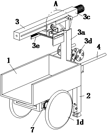
Structure of electric brick conveying vehicle

An electric and rotating rod technology, which is applied to motor vehicles, trolleys, single-axis trolleys, etc., can solve the problems of time-consuming and labor-intensive brick transportation, increase labor intensity of workers, etc., and achieve the effect of reducing labor intensity

CN108791380AActive Publication Date: 2018-11-13安徽省华建建设工程有限公司
13 Cites 5 Cited by

Patent Information

Authority / Receiving Office
CN · China
Patent Type
Applications(China)
Current Assignee / Owner
Publication Date
2018-11-13

Smart Images

  • Figure 1
    Figure 1
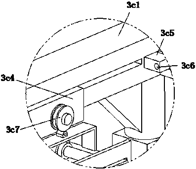
  • Figure 2
    Figure 2
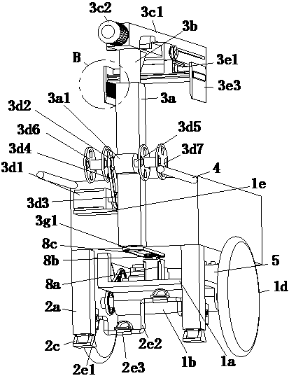
  • Figure 3
    Figure 3
Patent Text Reader

Abstract

The invention relates to the field of construction machinery equipment, in particular to an electric brick conveying vehicle. The electric brick conveying vehicle comprises a vehicle body, and a mounting frame is arranged at the bottom of the vehicle body. A mounting seat and a first rotary shaft are arranged at the bottom of the mounting frame, wherein a rotary hole is formed in the mounting seat, and vehicle wheels are arranged at the two ends of the first rotary shaft. A supporting device is arranged at the back end of the bottom of the vehicle body, a carrying device and two pushing handsarranged at intervals are arranged at the back end of the vehicle body, and the carrying device is located between the two pushing hands. A storage battery, a controller, a first drive device and a second drive device are arranged in the mounting frame, the first drive device is connected with the first rotary shaft in a transmission mode, the controller is electrically connected with the storagebattery, and the first drive device, the second drive device and the carrying device are electrically connected with the controller. The vehicle body can walk automatically through the first drive device, bricks can be carried automatically through the carrying device and the second drive device, the back end of the vehicle body can be lifted through the supporting device, and removing the bricksis convenient for workers. In conclusion, the labor intensity of the workers is greatly reduced.
Need to check novelty before this filing date? Find Prior Art

Description

technical field

[0001] The invention relates to the field of construction machinery and equipment, in particular to the structure of an electric brick transporter. Background technique

[0002] Artificial small blocks for construction are divided into sintered bricks and non-sintered bricks, commonly known as bricks; clay bricks are made of clay as the main raw material, which is processed, shaped, dried and roasted with mud. Bricks are an essential product for building houses. According to different parts used in construction projects, bricks are divided into wall bricks, floor bricks, arch shell bricks, floor bricks, sewer bricks and chimney bricks. When building large buildings, workers usually use a mobile brick truck to transport the fired bricks from the factory to the construction site, and unload the bricks in the open area. When the workers need to use bricks, the workers will use a manual brick transporter to transport the bricks to the designated place. The manua...

Examples

Embodiment Construction

[0027] The following will be combined with Figure 1 to Figure 8 The present invention is described in detail, and the technical solutions in the embodiments of the present invention are clearly and completely described. Apparently, the described embodiments are only some of the embodiments of the present invention, not all of them. Based on the embodiments of the present invention, all other embodiments obtained by persons of ordinary skill in the art without making creative efforts belong to the protection scope of the present invention.

[0028] The present invention provides a kind of electric brick transport vehicle here through improvement, as Figure 1-Figure 8As shown, including the vehicle body 1, the bottom of the vehicle body 1 is provided with a mounting frame 1a, and the bottom of the mounting frame 1a is provided with a mounting seat 1b and a first rotating shaft 1c, and the mounting seat 1b is provided with a shaft that is rotatably matched with the first rotati...