Intelligent outer wall cleaning machine
A cleaning machine and cleaning mechanism technology, which is applied in the directions of manipulators, building maintenance, and manufacturing tools, can solve the problems of easy deviation from the cleaning track, easy slipping of suction cups, waste of materials, etc., and achieve novel design, high safety, and convenient use.
- Summary
- Abstract
- Description
- Claims
- Application Information
AI Technical Summary
Problems solved by technology
Method used
Image
Examples
Embodiment 1
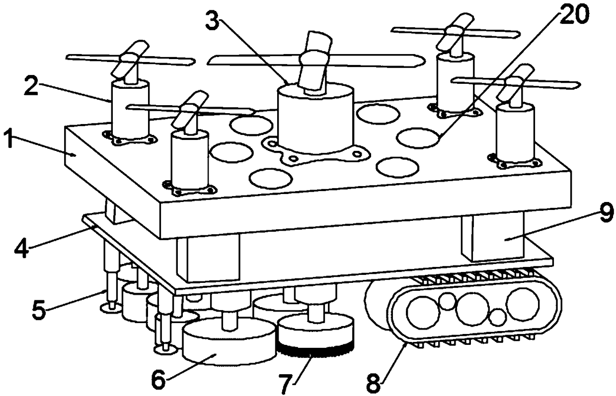
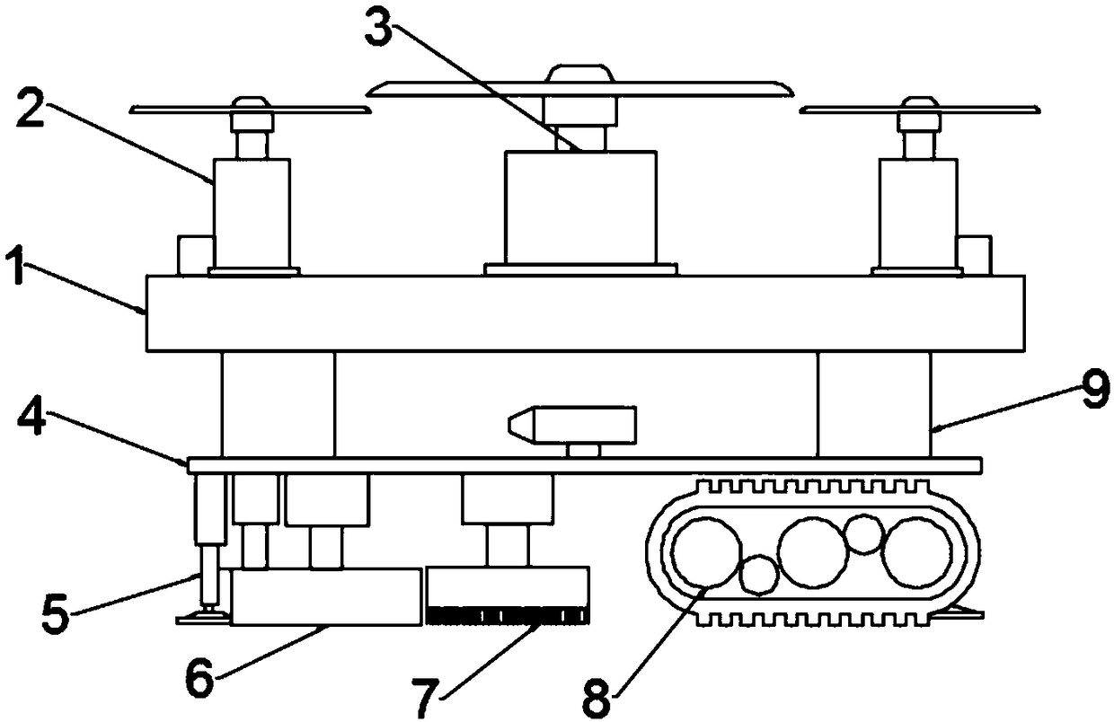
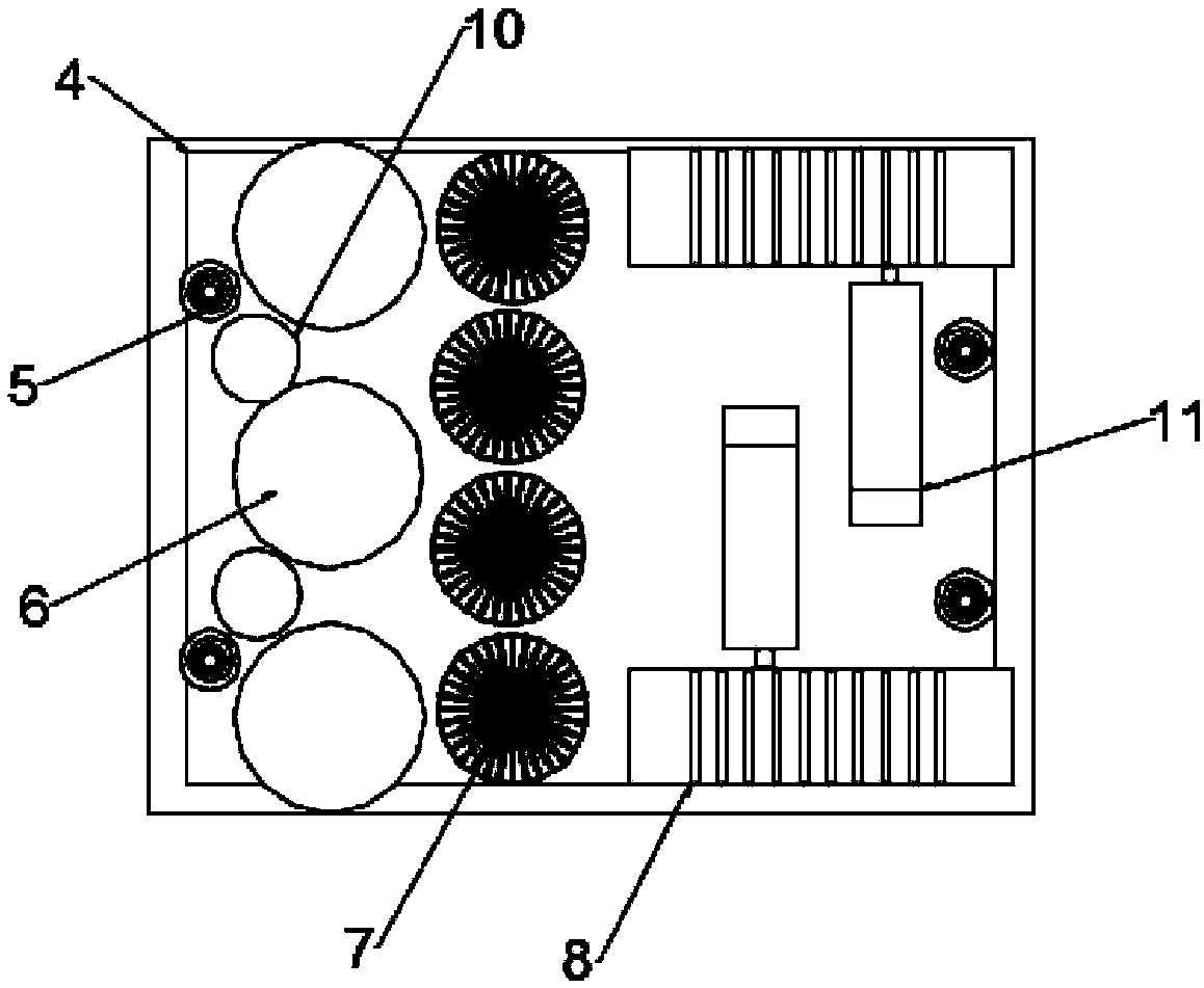
[0030] see Figure 1-10 , in an embodiment of the present invention, an intelligent exterior wall cleaning machine includes a robot body, a control system, and a winch; the robot body is connected to the winch through a connecting wire, and the winch drives the robot body to move when it works, and the electrical components in the robot body The wire is electrically connected to the control system, and the wire and the connecting wire are braided together to form a composite cable. The robot body includes a first mounting plate 1, a second mounting plate 4, an auxiliary fan 2, a main fan 3, a driving mechanism and a cleaning mechanism , the first mounting plate 1 and the second mounting plate 4 are fixed by a fixed block 9, the driving mechanism and the cleaning mechanism are installed at the lower end of the second mounting plate 4, and the four corners of the upper end of the first mounting plate 1 pass through The auxiliary fan 2 is fixedly installed on the motor base, and ...
Embodiment 2
[0045] The difference between the second embodiment and the first embodiment is that an auxiliary soft brush 10 is provided at the side end between the adjacent soft wool brushes 6, and the auxiliary soft brush 10 can soften the two adjacent wool brushes 6. Brushing in the middle position further improves the cleaning effect of the glass.
Embodiment 3
[0047] The difference between Embodiment 3 and Embodiment 1 is that a position adjustment mechanism is provided below the winch, and the position adjustment mechanism includes a movable plate 21, a support plate 22, a symmetrically arranged guide rail 23 and an adjustment motor 27, and the symmetrically arranged guide rail 23 is fixedly installed. Between the two support plates 22, the movable plate 21 is slidably connected with the guide rail 23 through the sliding sleeve 24 fixed on its lower end. A threaded rod 25 is arranged in the middle of the two guide rails 23, and the two ends of the threaded rod 25 are connected with the two support plates respectively. 22 fixed.
[0048] The inner side of the movable plate 21 is provided with a placement groove 26, the adjusting motor 27 is fixed in the placement groove 26 by the motor mount, and the output shaft of the adjusting motor 27 rotates through the transmission belt 30 and the threaded sleeve 29 sleeved on the threaded rod ...
PUM
 Abstract
Description
Claims
Application Information
 - R&D
- Intellectual Property
- Life Sciences
- Materials
- Tech Scout
- Unparalleled Data Quality
- Higher Quality Content
- 60% Fewer Hallucinations
Browse by: Latest US Patents, China's latest patents, Technical Efficacy Thesaurus, Application Domain, Technology Topic, Popular Technical Reports.
© 2025 PatSnap. All rights reserved.Legal|Privacy policy|Modern Slavery Act Transparency Statement|Sitemap|About US| Contact US: help@patsnap.com


