Methods and system for central fuel injection

A fuel injector and fuel technology, which is applied in the directions of low pressure fuel injection, fuel injection device, fuel injection control, etc., can solve the problems of emission quality and fuel economy.

Active Publication Date: 2018-11-13
FORD GLOBAL TECH LLC
View PDF6 Cites 2 Cited by
  • Summary
  • Abstract
  • Description
  • Claims
  • Application Information

AI Technical Summary

Problems solved by technology

Therefore, emission quality may be adversely affected by
Furthermore, the need for additional fueling to purge the catalyst adversely affects fuel economy

Method used


Image

  • Methods and system for central fuel injection
  • Methods and system for central fuel injection
  • Methods and system for central fuel injection

Examples


Embodiment Construction

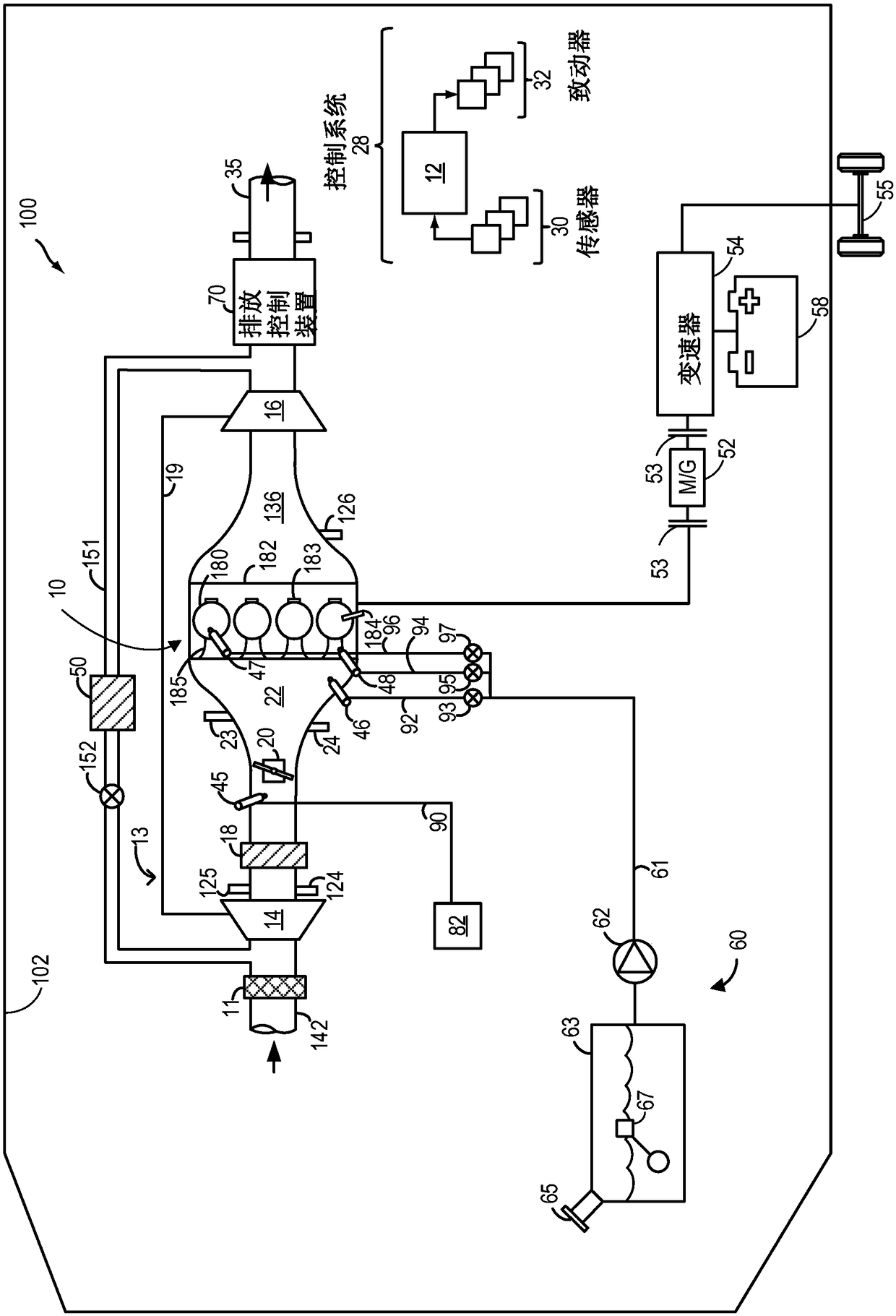
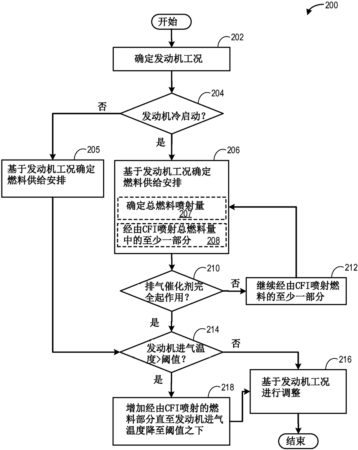
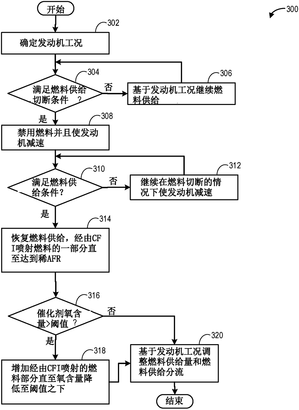
[0017] The following description relates to systems and methods for utilizing manifold fuel injection for increasing charge air cooling, for reducing NOx emissions, and for pre-ignition mitigation. The methods herein can be applied to engine systems with manifold, direct and port fuel injection capabilities such as figure 1 engine system). The engine controller can be configured to execute control programs such as figure 2 , image 3 and Figure 5 example routines) to adjust fueling schedules (including adjusting the amount of fuel delivered via manifold injection relative to the amount of fuel delivered via port injection and / or direct injection), for reducing NOx production and for pre-ignition mitigation. exist Figure 4 and Figure 8 An example adjustment of the fueling schedule to achieve desired charge cooling for NOx reduction and pre-ignition mitigation is shown at . exist Figure 6 and Figure 7 An example of fuel split ratios between manifold injection and p...


PUM


Abstract

The invention provides methods and system for central fuel injection. Methods and systems are provided for adjusting engine operating conditions for reduction of NOx emissions. In one example, immediately after a fuel shut-off event, in response to an oxygen content of an exhaust catalyst being higher than a threshold, manifold charge cooling may be increased by increasing the portion of fuel delivered to the engine via manifold injection relative to the portion to fuel delivered via one or more of port and direct injection. By increasing manifold cooling, NOx production may be reduced.

Description

technical field [0001] The present invention generally relates to methods and systems for adjusting manifold fuel injection to reduce NOx emissions. Background technique [0002] Internal combustion engines may include a central fuel injection (CFI) system that injects fuel into an intake manifold. When fuel is injected into the engine intake, heat is transferred from the intake air and / or engine components to the fuel, and this heat transfer results in atomization of a portion of the fuel, which results in cooling of the engine components. Injecting fuel into the intake air (eg, in the intake manifold, intake port, etc.) reduces both the intake air temperature and the combustion temperature at the engine cylinders. By cooling the intake charge, NOx production can be reduced. NOx is stored in an exhaust catalyst that is periodically or timely regenerated during rich-to-stoichiometric operation. In addition to CFI, fuel may also be injected into the intake runner via port ...

Claims


Application Information

Patent Timeline
Patent Type & Authority Applications(China)
IPC IPC(8): F02D41/06F02D41/14F02D41/30
CPCF02D41/064F02D41/1454F02D41/1458F02D41/3094F02D2250/36F01N9/00F01N2900/1624F02D41/0255F02M25/028F02M26/06F02D2200/0414F02D2200/0814F02M69/046F01N2560/025F01N2900/1402F01N2900/1602F01N2900/1606F01N2900/1626F02D41/023F02D41/0295F02D41/126F02D41/1461Y02T10/40F01N3/021F01N3/10F01N3/36F01N11/002F01N11/007F01N2250/02F01N2430/06F01N2560/06F01N2900/08F01N2900/1614F02D41/0087F02D41/0235F02D41/10F02D41/12F02D41/123F02D41/1441F02D41/1456F02D41/146F02D41/1495F02D2041/001F02D2200/1002F02D2200/101
Inventor G·苏妮拉A·P·R·兰加M·哈基姆C·特瑞斯科特J·N·尤瑞尔P·C·莫莱恩
Owner FORD GLOBAL TECH LLC
Why Eureka
Try Eureka