Working face mining rock stratum damage underground top and bottom plate drilling electric method monitoring method

A working face, roof and floor technology, which is applied in the field of coal seam exploration, can solve the problems of poor electrical data quality, cable breakage, and the monitoring system cannot monitor for a long time, and achieves the effect of improving reliability and increasing the space range.

Inactive Publication Date: 2018-11-13
ANHUI UNIV OF SCI & TECH
View PDF0 Cites 5 Cited by
  • Summary
  • Abstract
  • Description
  • Claims
  • Application Information

AI Technical Summary

Problems solved by technology

In the goaf, the rock formation failure zone does not enter the double borehole monitoring area, and only the change of mining advance stress can be monitored; after the rock formation failure zone enters the double borehole monitoring area, the collapse zone or crack zone reaches the drilling position Afterwards, the coupling conditions of the borehole electrode often deteriorate, resulting in a significant deterioration of the electrical data quality, and poor reflection of the resistivity image on the caving and fr

Method used


Image

  • Working face mining rock stratum damage underground top and bottom plate drilling electric method monitoring method
  • Working face mining rock stratum damage underground top and bottom plate drilling electric method monitoring method
  • Working face mining rock stratum damage underground top and bottom plate drilling electric method monitoring method

Examples


Embodiment 1

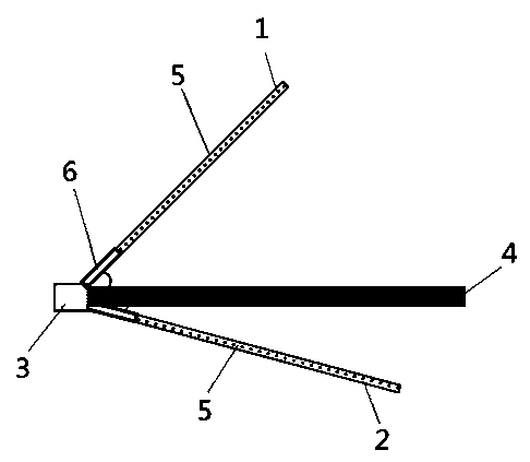
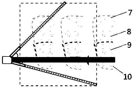
[0035] like figure 1 , figure 2 as shown, figure 1 Including 1# hole 1, 2# hole 2, roadway 3, coal seam 4, cable 5, casing 6, figure 2 Including bending subsidence zone 7, crack zone 8, collapse zone 9, floor failure zone 10. Figure 5 The dotted box in the middle is the control range of the electrical method, and the arrow points to the mining direction of the working face.

[0036] Roof and floor monitoring specifically includes the following steps:

[0037] 1. Drilling control height design: According to the geological conditions of the coal mining face, and in accordance with the 2015 energy industry standard of the People's Republic of China "Measurement Method for Dynamic Apparent Resistivity of Coal Mining Overlying Rock Destruction", calculate the height of the expected collapse zone and crack zone, Obtain the control height of borehole 1 in design 1#.

[0038] 2. Selection of drilling location: Select a suitable drilling construction location 300m in front of t...

Embodiment 2

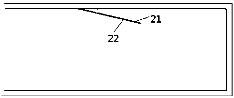
[0046] This embodiment is the roof monitoring method in the prior art. like image 3 , Figure 4 , Figure 5 As shown, the figure includes 1# hole 21 and 2# hole 22.

[0047] Subsurface formations with different lithologies usually have different characteristics of resistivity values. The drilling electrical monitoring range can be arranged at a certain position in the upper roadway or the lower roadway on the coal mining face to monitor the change of resistivity value. The plane projection position of the drilling end point should be more than 100m away from the coal cutting position. The current electrical monitoring method for overlying rock damage in underground boreholes is to arrange a pair of boreholes on the roof. The two boreholes coincide or can be regarded as coincident on the plane, and have different borehole elevation angles on the vertical surface. floor plan as image 3 As shown, the vertical section is arranged as Figure 4shown. The height of the final...


PUM

PropertyMeasurementUnit
Hole depthaaaaaaaaaa

Abstract

The invention discloses a working face mining rock stratum damage underground top and bottom plate drilling electric method monitoring method, and belongs to the technical field of coal seam exploration methods. The method comprises the following steps: step one, determining the profile position of a drilling plane; step two, determining drilling parameters; step three, laying drilling electrode cables; step four, constructing a drilling monitoring system; and step five, acquiring data. According to the monitoring method, an electric method monitoring and control scope between double drilled holes is expanded, so that development of a caving zone or a fracture zone cannot affect electrode coupling of drilling cables quickly, dynamic change of electrical resistivity can be monitored for a long time, a dynamic development process of the caving zone and the fracture zone is fully reflected, and the reliable heights of the carving zone and the fracture zone are obtained.

Description

technical field [0001] The invention relates to the technical field of coal seam exploration methods, in particular to an electrical monitoring method for drilling rock formations in mining face damage to underground roof and floor plates. Background technique [0002] After the coal seam is mined, rock deformation and failure will occur under the action of in-situ stress, forming a floor failure zone on the floor; and a caving zone, crack zone and bending subsidence zone on the roof. The collapse zone and the fracture zone are collectively called the water-conducting fracture zone. The development height and process of the caving zone and the fracture zone are of great significance for raising the upper limit of recovery in the coal seam working face, preventing and controlling roof water hazards, managing roof strata, and preventing and controlling gas. [0003] The control range of the current downhole roof drilling electrical monitoring device is relatively small, espec...

Claims


Application Information

Patent Timeline
IPC IPC(8): G01V3/20
CPCG01V3/20
Inventor 吴荣新张平松肖玉林胡雄武付茂如胡泽安
Owner ANHUI UNIV OF SCI & TECH
Why Eureka
Try Eureka